Autonomous electronic device with supply by electrostatic transduction produced by a variable capacitor

Active Publication Date: 2017-06-22
CENT NAT DE LA RECHERCHE SCI +1
View PDF0 Cites 1 Cited by
  • Summary
  • Abstract
  • Description
  • Claims
  • Application Information

AI Technical Summary

Benefits of technology

[0025]A purpose of the invention is to supply an electronic device capable of converting ambient mechanical energy to electrical energy for its supply, in its entirety or as a suppl

Problems solved by technology

Electronic devices of this kind may be for example devices with low consumption intended to be implanted in the human or animal body, for which it is impossible or complicated to provide an electrical connection for recharging.
This manner of transduction passes through an electronic energy management circuit that can be miniaturized, but currently requires complex electronics for managing the charge and discharge cycles of the transducer.
Now, in the known devices, operation of such an energy management circuit requires several tens of volts and represents a sizable consumption, whereas the power levels generated by

Method used


Image

  • Autonomous electronic device with supply by electrostatic transduction produced by a variable capacitor
  • Autonomous electronic device with supply by electrostatic transduction produced by a variable capacitor
  • Autonomous electronic device with supply by electrostatic transduction produced by a variable capacitor

Examples


first embodiment

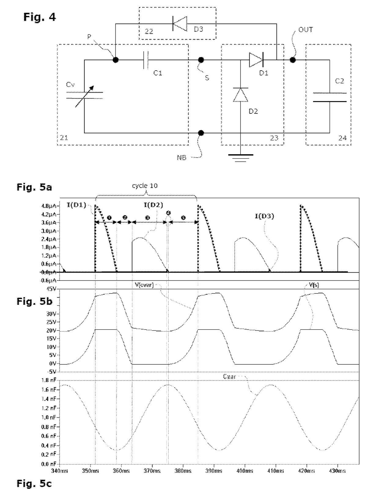
[0117]FIG. 4 shows the power supply circuit of a device according to the invention, in a first embodiment, called “basic circuit” here.

[0118]In this embodiment, the power supply circuit comprises the following elements, and preferably only these:

[0119]a generating branch 21 comprising the variable capacitor Cv and one or more biasing capacitors C1, and preferably only these latter (and preferably only one). This generating branch is connected via its base node NB to a reference potential, which is earth here, by a node that is common to the rectifier 23 and to the storage branch 24;

[0120]a rectifier circuit 23 comprising the following components, and preferably only these:[0121]a diode D2 (preferably just one), or several diodes mounted in the same direction (preferably in series), from the base node NB to the end S of the generating branch that is located on the biasing capacitor C1 side,[0122]a diode D1 (preferably just one), or several diodes mounted in the same direction (prefer...

second embodiment

[0157]FIG. 7 shows the power supply circuit of a device according to the invention, in a second embodiment forming an inverted version of the basic circuit in FIG. 4.

[0158]In this device, the power supply circuit comprises the following elements, and preferably only these:

[0159]a generating branch 21 comprising the variable capacitor Cv and one or more biasing capacitors C1, and preferably only the latter (and preferably only one), said generating branch being earthed via the base node NB;

[0160]a rectifier circuit 23 comprising the following components, and preferably only these:[0161]a diode D2′ (preferably only one), or several diodes mounted in the same direction (preferably in series), to the base node NB and from the output node S of the end of the generating branch 21 located on the biasing capacitor C1 side,[0162]a diode D1′ (preferably only one), or several diodes mounted in the same direction (preferably in series), to the output node S of the end of the generating branch 2...

third embodiment

[0167]FIG. 8 shows the power supply circuit of a device according to the invention, in a third embodiment based on the basic circuit and in which the storage capacitor is of a mid-point type connected to the rectifier.

[0168]The power supply circuit of this device comprises an electrical energy storage component (preferably formed by two capacitors connected in series) having a point that is intermediate in voltage, forming for example a mid-point, which is connected to the base node NB and thus delimits:

[0169]a first storage part C2 which forms the storage element of the storage branch 24; and

[0170]a second storage part C3 which is connected in series in the rectifier circuit 23 between the base node NB and the biasing node S located in the generating branch 21 between the variable capacitor Cv and the biasing capacitor C1.

[0171]In this configuration, the voltage Vmax is equal to 3 / 2*Vout and the voltage Vmin is equal to 1 / 2*Vout.

[0172]The energy converted per cycle is therefore exp...


PUM


Abstract

An electronic device with a circuit for supplying electric power, with a variable capacitor, by alternating mechanical movement. The supply includes, in the form of passive components and without synchronizing structure:
    • generating branch including in series the variable capacitor and a biasing capacitor, connected in parallel to a rectifier circuit and a storage branch, between:
    • a base node, on the variable capacitor;
    • an output node, on the biasing capacitor side;
    • unidirectional charge return branch:
    • to the generating branch, via a biasing node between the variable capacitor and the biasing capacitor;
    • from the rectifier, receiving a part of the electrical energy produced.
A circuit includes a voltage multiplier connected to the biasing node for applying a voltage that is multiplied relative to that existing between
    • the output node, and
    • the base node or one of the ends of the storage branch.

Description

[0001]The invention relates to an electronic device of the type operating without an external power supply and comprising an electric power supply circuit comprising at least one variable capacitor, under the effect of an alternating mechanical movement, connected to a storage device by a rectifier circuit. This power supply circuit comprises, in the form of passive components and without synchronizing means:[0002]a generating branch comprising the variable capacitor and a biasing capacitor connected in series, said branch being mounted in parallel with the rectifier circuit and with a storage branch, between:[0003]a node, called base node, at the end of the generating branch on the variable capacitor side,[0004]a node, called output node, at the end of the generating branch on the biasing capacitor side;[0005]a unidirectional charge return branch:[0006]to the generating branch at a biasing node located between the variable capacitor and the biasing capacitor;[0007]from the rectifie...

Claims


Application Information

Patent Timeline
IPC IPC(8): H02J7/00A61N1/378A61B5/07H02N1/08H02M7/10
CPCH02J7/0068H02N1/08H02M7/10A61B2560/0214A61N1/3787H02J7/345A61B5/07H02J7/32H02J7/34H02N2/181H02J2207/20Y02B40/00
Inventor LEFEUVRE, ELIE
Owner CENT NAT DE LA RECHERCHE SCI
Why Eureka
Try Eureka