
Apparatus and method for allocating bits temporaly between frames in a coding system

a technology of coding system and apparatus, applied in the field of apparatus and method for allocating bits, can solve the problems of affecting the distortion of input video image, reducing the high cost of video compression codec (coder/decoder) and resolving the inter-operability of equipment, and affecting so as to achieve the effect of reducing the visual quality of video image, poor rate control process, and reducing the cost of video compression cod

Inactive Publication Date: 2005-05-17
MEDIATEK USA INC
View PDF3 Cites 58 Cited by
  • Summary
  • Abstract
  • Description
  • Claims
  • Application Information

AI Technical Summary

Benefits of technology

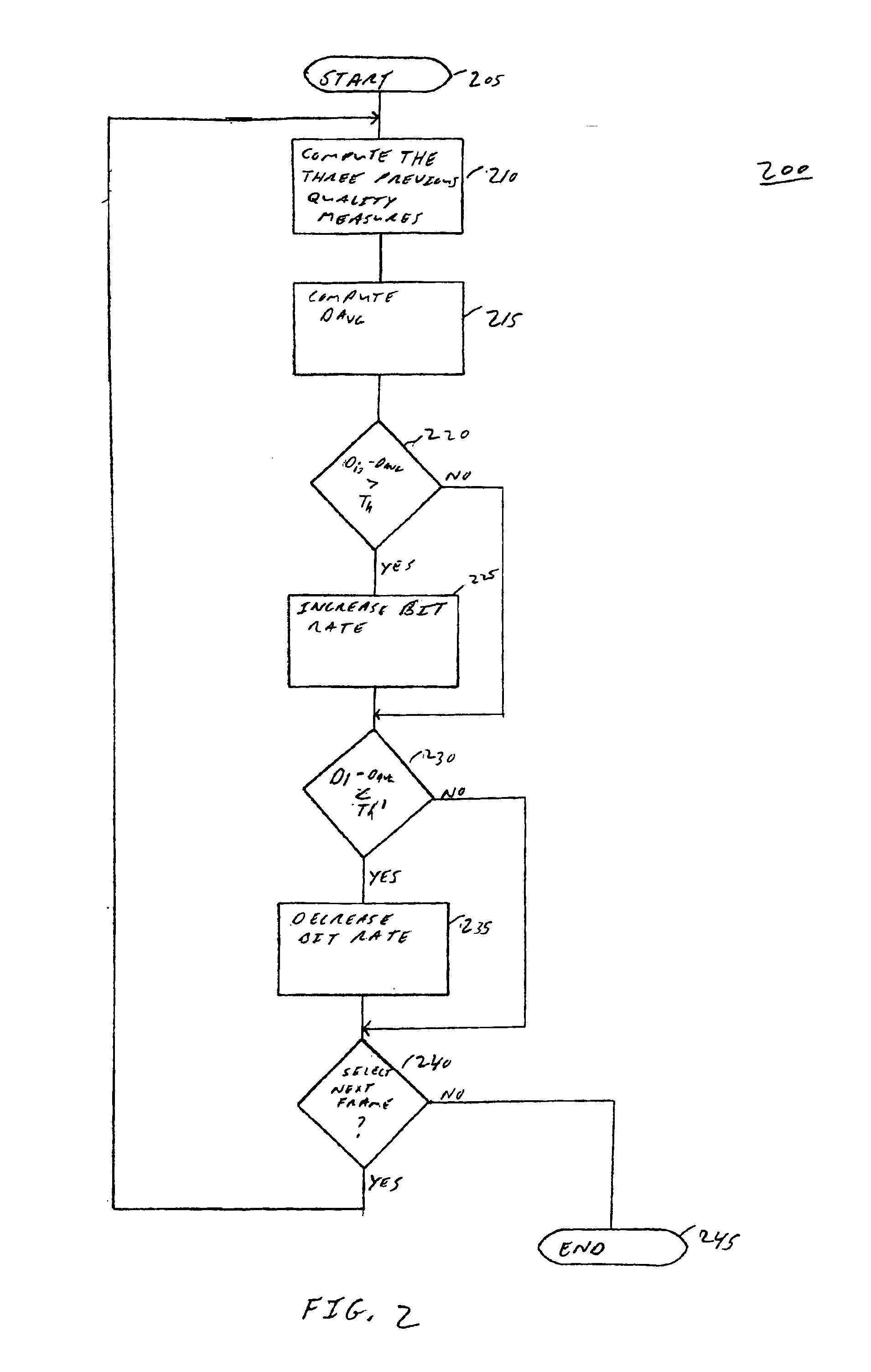
[0010]The present invention is a method and apparatus for temporally allocating bits between frames of an image sequence in a coding system such that temporal fluctuations are smoothed out. Namely, a picture quality is monitored on a frame by frame basis. In one embodiment, an average distortion measure is derived from several previous picture frames and this temporal average distortion measure is compared to the distortion measure of a current frame. The difference of this comparison is measured against a predefined threshold, where the result is used to control the bit allocation for the current frame. In an alternative embodiment, the present method is applied in conjunction with a wavelet transform.

Problems solved by technology

The increasing development of digital video technology presents an ever increasing problem of reducing the high cost of video compression codecs (coder / decoder) and resolving the inter-operability of equipment of different manufacturers.
Currently, one way of controlling the bit rate is to alter the quantization process, which will affect the distortion of the input video image.
Although changing the quantizer scale is an effective method of implementing the rate control of an encoder, it has been shown that a poor rate control process will actually degrade the visual quality of the video image.
However, the quantizer scale selected by this criterion may not achieve optimal coding performance, since the complexity of each picture will vary with time.
Furthermore, encoders that utilize global-type transforms have similar problems.

Method used


Image

  • Apparatus and method for allocating bits temporaly between frames in a coding system
  • Apparatus and method for allocating bits temporaly between frames in a coding system
  • Apparatus and method for allocating bits temporaly between frames in a coding system

Examples


Embodiment Construction

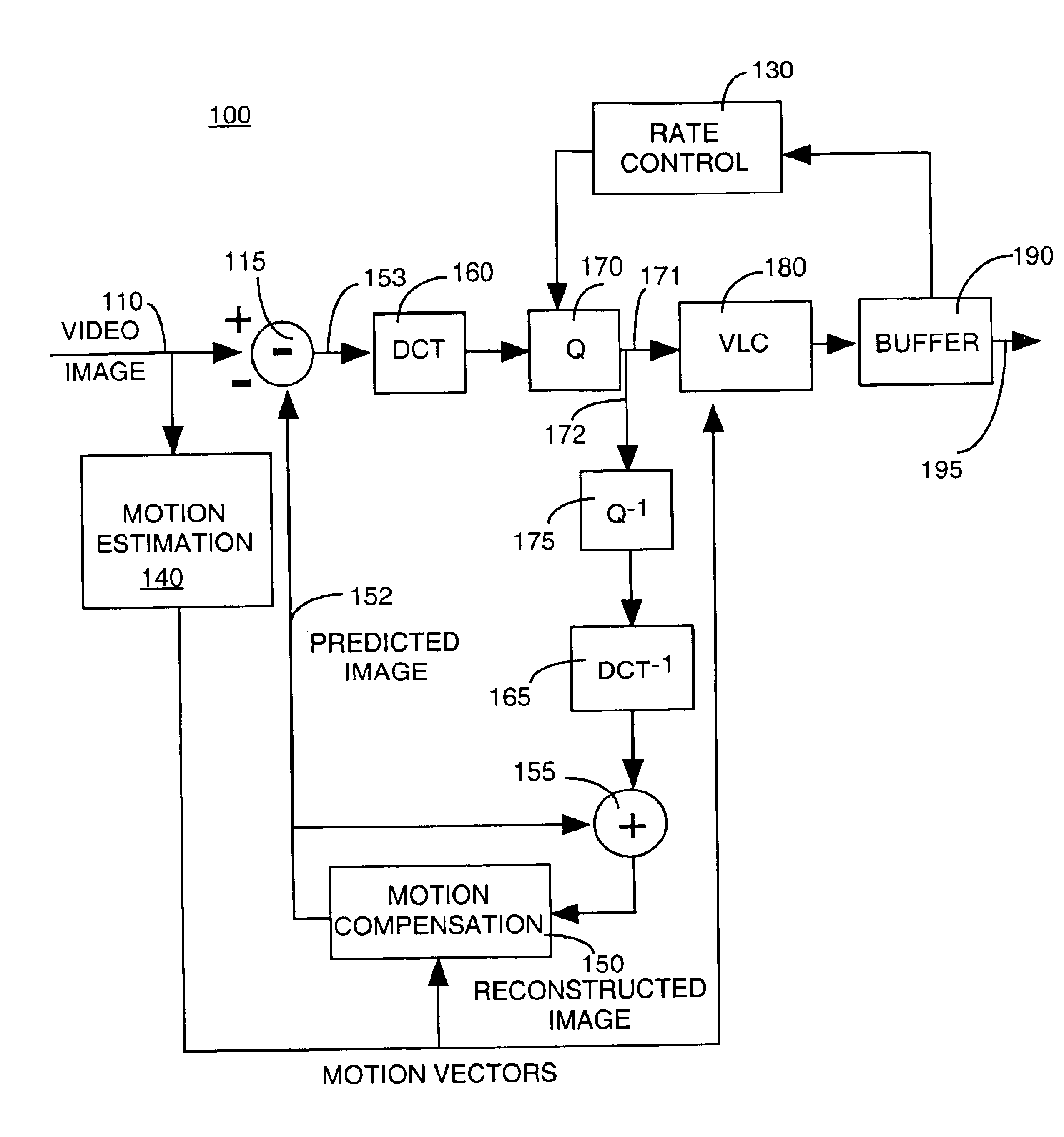
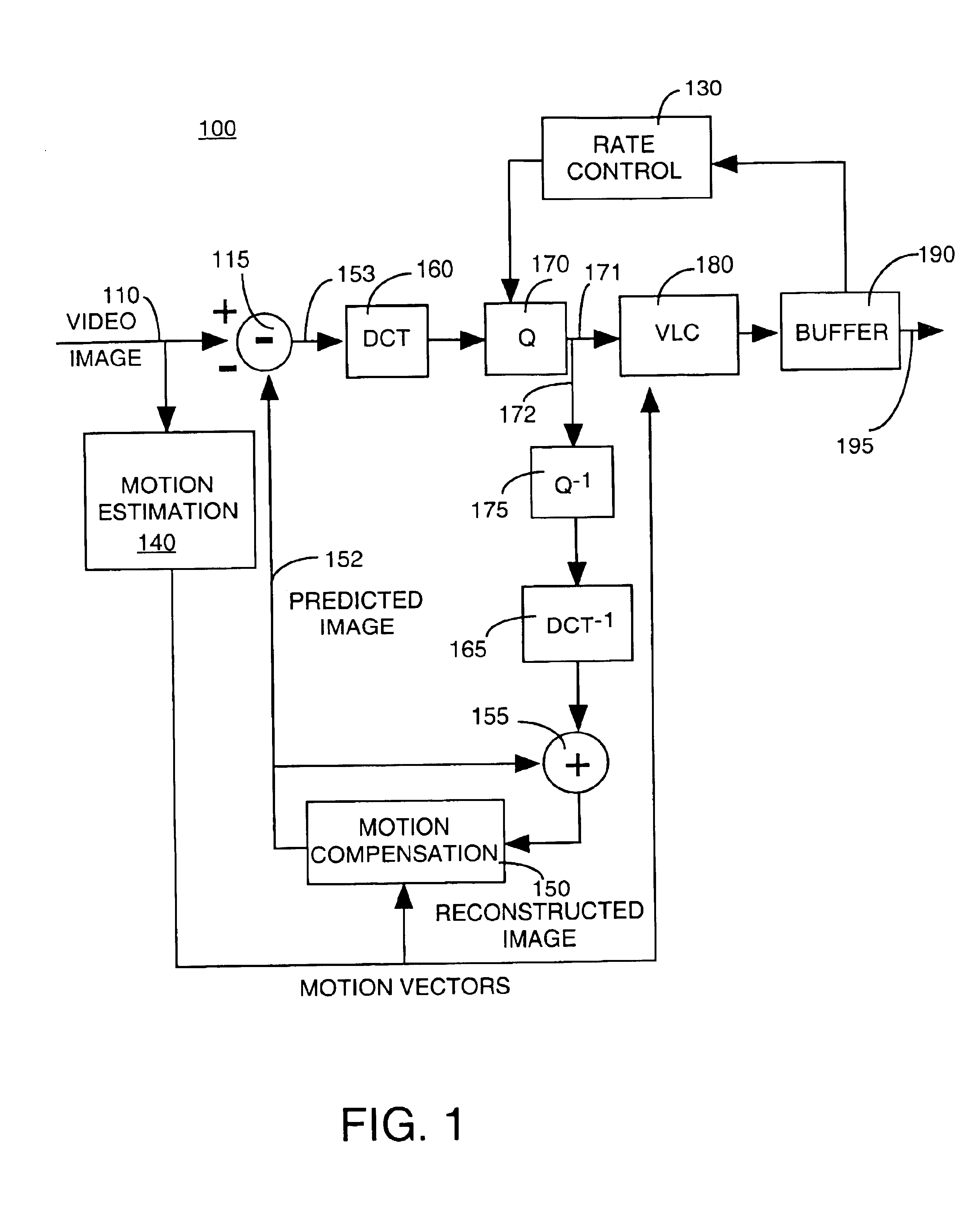
[0018]FIG. 1 depicts a block diagram of the apparatus 100 of the present invention for using a picture quality or distortion measure to temporally allocate bits in an encoding system. In the preferred embodiment of the present invention, the apparatus 100 is an encoder or a portion of a more complex block-based motion compensation coding system. The apparatus 100 comprises a motion estimation module 140, a motion compensation module 150, a rate control module 130, a DCT module 160, a quantization (Q) module 170, a variable length coding (VLC) module 180, a buffer 190, an inverse quantization (Q−1) module 175, an inverse DCT (DCT−1) transform module 165, a subtractor 115 and a summer 155. Although the apparatus 100 comprises a plurality of modules, those skilled in the art will realize that the functions performed by the various modules are not required to be isolated into separate modules as shown in FIG. 1. For example, the set of modules comprising the motion compensation module 1...


PUM


Abstract

A method and apparatus for temporally allocating bits between frames in a coding system such that temporal fluctuations are smoothed out. Namely, a picture quality is monitored on a frame by frame basis. An average distortion measure is derived from previous picture frames and that average is compared to the distortion measure of a current frame, where the result is used to effect bit budget allocation for each frame in an input image sequence.

Description

GOVERNMENT RIGHTS IN THIS INVENTION[0001]This invention was made with U.S. government support under contract number NIST contract 70NANB5H1178. The U.S. government has certain rights in this invention.[0002]The present invention relates to an apparatus and concomitant method for optimizing the coding of an image sequence, e.g., motion video. More particularly, this invention relates to a method and apparatus that temporally allocates bits (i.e., bit budget) between frames of an image sequence to be encoded by a coding system.BACKGROUND OF THE INVENTION[0003]The increasing development of digital video technology presents an ever increasing problem of reducing the high cost of video compression codecs (coder / decoder) and resolving the inter-operability of equipment of different manufacturers. To achieve these goals, the Moving Picture Experts Group (MPEG) created international standards 11172 and 13818, which are incorporated herein in their entirety by reference.[0004]In the area of ...

Claims


Application Information

Patent Timeline
Patent Type & Authority Patents(United States)
IPC IPC(8): H04N7/26H04N7/30
CPCH04N19/176H04N19/147H04N19/172H04N19/149H04N19/63H04N19/64H04N19/60H04N19/124H04N19/14H04N19/152H04N19/61H04N19/115H04N19/146
Inventor LEE, JUNGWOO
Owner MEDIATEK USA INC
Learn More