In-line lead header for an implantable medical device

a medical device and lead header technology, applied in the direction of coupling contact members, coupling device connections, therapy, etc., can solve the problems of limited ability to reduce overall size, difficult assembly and use, disclosed embodiments, etc., and achieve the effect of facilitating the insertion of continuous coil springs

Inactive Publication Date: 2005-05-17
MEDTRONIC INC
View PDF24 Cites 235 Cited by
  • Summary
  • Abstract
  • Description
  • Claims
  • Application Information

AI Technical Summary

Benefits of technology

[0019]Each electrical connector element is formed with an annular U-shaped interior channel defined between connector element annular end walls into which a connector spring element is fitted. The spring element can comprise a continuous coil spring of the types disclosed in the above-referenced '270 and '246 patents and WO 00 / 64535 publication that is retained or trapped in the channel and that intrudes slightly into the stack bore whereby the spring element is compressed by a lead connector element inserted into the stack bore. The fluid seal is formed with one or more annular sealing ring formed in the seal lumen having a smaller diameter than the seal lumen so that the sealing ring intrudes slightly into the stack bore whereby the sealing ring is compressed by a lead insulator inserted into the stack bore. In this way, secure, frictional electrical and mechanical contact is made between lead connector elements and the header connector elements, and the sealing rings seal the electrical connections from fluid ingress.
[0021]In a second embodiment, the tubular connector elements are formed in two parts that are fitted together. The first part comprises one of the connector element end walls that define the U-shaped channel when the parts are fitted together. This embodiment facilitates insertion of the continuous coil spring into the U-shaped channel.

Problems solved by technology

The use of a setscrew to attach each respective lead and IPG connector element together limits the ability reduce overall size.
While a high degree of miniaturization of the IPG header is achieved, the embodiments disclosed in the '141 patent have proven difficult to assemble and use.

Method used


Image

  • In-line lead header for an implantable medical device
  • In-line lead header for an implantable medical device
  • In-line lead header for an implantable medical device

Examples


Embodiment Construction

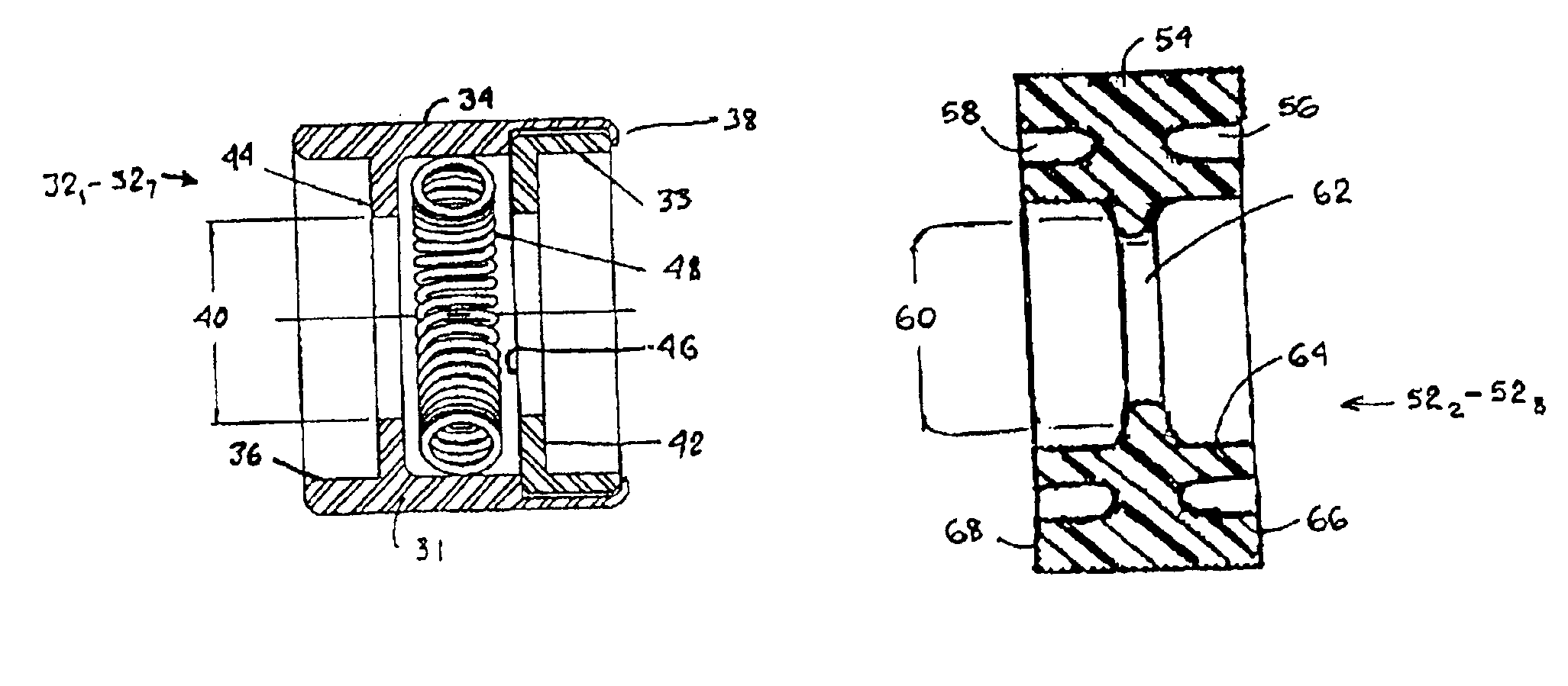
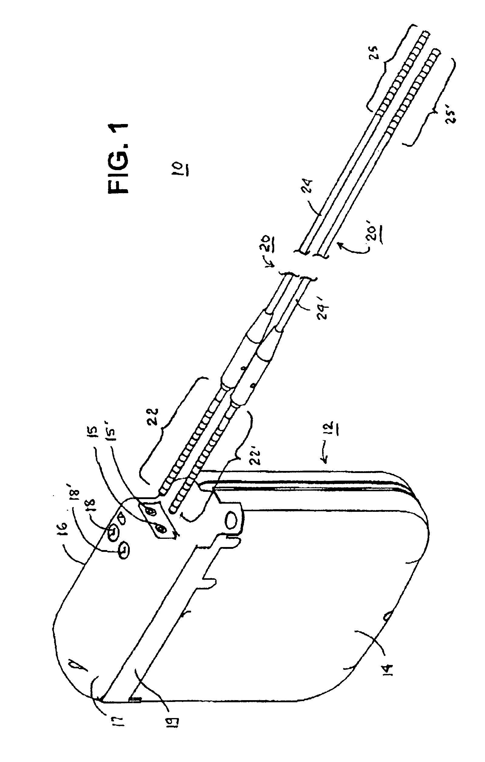
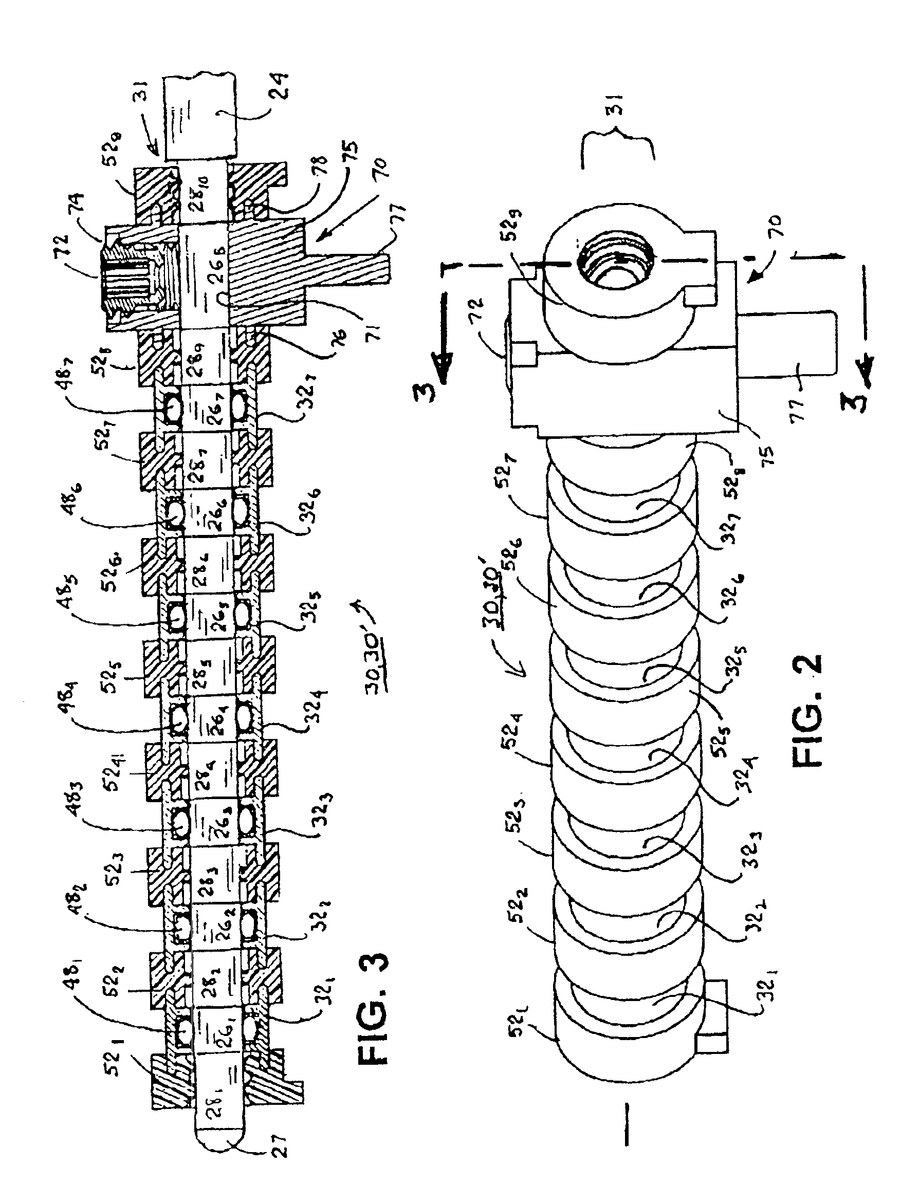
[0038]The present invention can be implemented in a wide variety of IMDs currently existing or that may come into existence that require the attachment of connector elements an elongated medical lead or other elongated medical instrument with a further part of the medical device. For convenience and not by way of limitation, the present invention is described in the context IMDs 10, 100 comprising: (1) an IPG 12 comprising an IPG housing 14, 114 and IPG header or header 16, 116; and (2) an electrical medical lead 20, 20′, 120. Electrical feedthroughs extending through the IPG housing 14, 114 couple the electronic circuitry with one or more IPG header connector elements that electrically and mechanically engage the lead connector elements. The electronic circuitry provides stimulation therapies through the electrodes (not shown in the figures) and / or processes signals picked up through the lead-borne electrodes and / or sensors (not shown in the figures). Thus, the term “IPG” in the sp...


PUM


Abstract

Implantable medical devices (IMDs) comprising a monitor or implantable pulse generator (IPG) having an IPG header to which lead connector assemblies of electrical medical leads are coupled, particularly, an improved in-line IPG header providing enhanced durability, ease of manufacture, and ease of use. A stack of alternating, substantially tubular electrically insulating fluid seals and header connector elements is assembled in axial alignment to form a common, elongated axial stack bore sized in diameter and length to receive the lead connector assembly. Each adjacent electrical connector element and fluid seal are interlocked with one another during assembly of the stack to maintain the axial alignment and the length and diameter dimensions. Fluid seals are located at each end of the stack, and the stack can be inserted as a unit into a cavity of the IPG header.

Description

FIELD OF THE INVENTION[0001]This invention relates generally to implantable medical devices (IMDs) comprising a monitor or implantable pulse generator (IPG) having an IPG header to which lead connector assemblies of electrical medical leads are coupled, and particularly, to improved in-line lead IPG headers providing enhanced durability, ease of use, and ease of manufacture.BACKGROUND OF THE INVENTION[0002]A wide variety of IMDs that employ electronic circuitry for providing electrical stimulation of body tissue and / or monitoring a physiologic condition are known in the art. A number of IMDs of various types are known in the art for delivering electrical stimulation therapies to selected body tissue and typically comprise an IPG for generating stimulating therapies and at least one electrical medical lead bearing a stimulation electrode for delivering the stimulating pulses to the selected tissue. For example, cardiac pacemakers and implantable cardioverter-defibrillators (ICDs) hav...

Claims


Application Information

Patent Timeline
Patent Type & Authority Patents(United States)
IPC IPC(8): A61N1/372A61N1/375H01R24/04H01R24/00H01R13/115A61N1/32H01R13/11H01R24/58
CPCA61N1/3752H01R24/58H01R13/111Y10S439/909H01R2107/00H01R2201/12
Inventor KAST, JOHN E.RIES, ANDREW J.GRIMES, KELLY
Owner MEDTRONIC INC
Why Eureka
Try Eureka