
Thread-guiding device for collecting spun yarns on bobbins particularly for open-end spinning frames

a technology of spinning frame and thread guide, which is applied in the field of spinning, can solve the problems of impediments to use and the inability of yarn on the bobbin with grooved cylinder to meet the conditions

Inactive Publication Date: 2005-05-24
SAVIO MACCHINE TESSILI
View PDF12 Cites 2 Cited by
  • Summary
  • Abstract
  • Description
  • Claims
  • Application Information

AI Technical Summary

Benefits of technology

[0038]The object of the present invention is to produce a device to distribute the spun yarn on bobbins being wound which overcomes the drawbacks of thread-guiding devices available at the state of the art and makes it possible to obtain bobbins with more regular density, shape and stability.

Problems solved by technology

Typically, distribution of the spun yarn on the bobbin with modulatable thread-guide is required in open-end spinning frames, for which distribution of the spun yarn on the bobbin with grooved cylinder does not meet the conditions required for efficacious winding on a bobbin of the desired quality.
There are also other impediments to the use of the grooved cylinder, both due to the geometry of the system and to the overall open-end spinning procedure.

Method used


Image

  • Thread-guiding device for collecting spun yarns on bobbins particularly for open-end spinning frames
  • Thread-guiding device for collecting spun yarns on bobbins particularly for open-end spinning frames
  • Thread-guiding device for collecting spun yarns on bobbins particularly for open-end spinning frames

Examples


Embodiment Construction

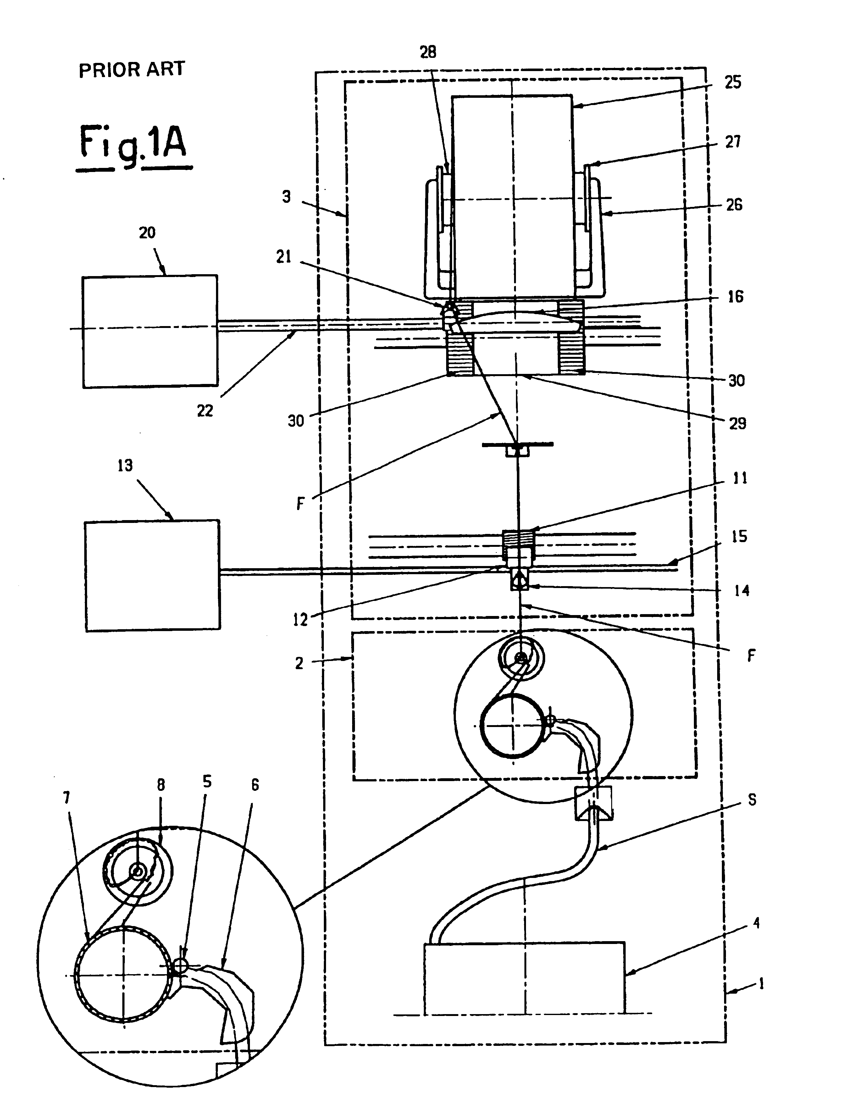
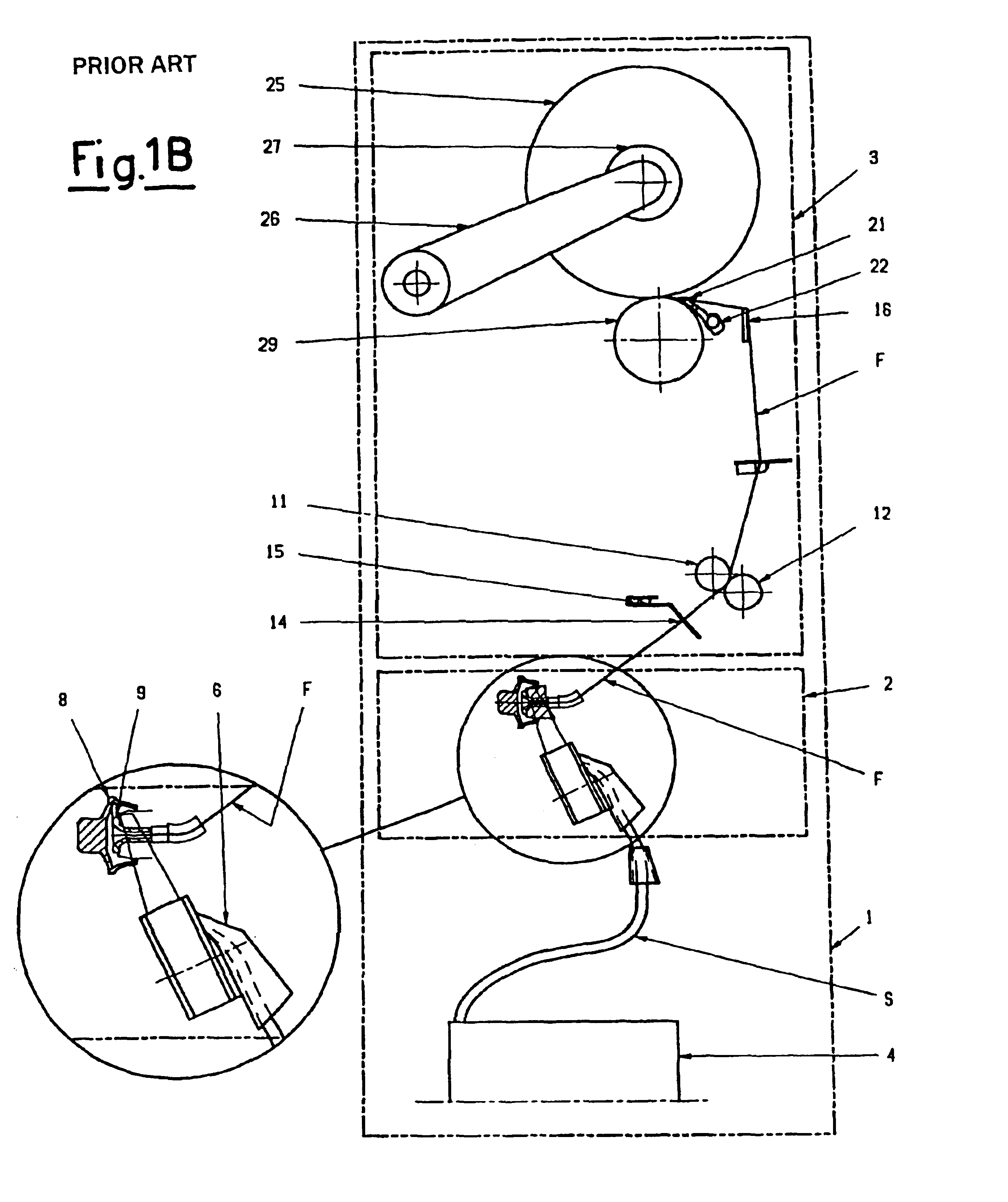
[0014]Proceeding from the bottom upward, we first encounter the spinning unit 2 and then the pick-up unit 3, the main components of which used to transform staple parallel fibres into the bobbin of wound spun yarn are illustrated briefly below.

[0015]The feed strip or staple S is contained in a cylindrical vessel 4 where it is deposited in a double spiral. The staple S is taken up from this and fed to the unit by a feed roller 5 passing through the condenser / funnel conveyor 6. The strip S then passes to the card 7, which rotates at high speed to separate and select the fibres of the staple S and convey then by suction to the spinning rotor 8. In this path the short fibres and impurities are separated, so that only the long and cleanest fibres reach the rotor. The impurities are unloaded into a suction outlet common to all the spinning units.

[0016]In the spinning rotor 8, which rotates at a speed ωR which reaches 100,000 rpm and over, the fibres are deposited in its peripheral groove ...


PUM

PropertyMeasurementUnit
speedaaaaaaaaaa
shapeaaaaaaaaaa
lengthaaaaaaaaaa

Abstract

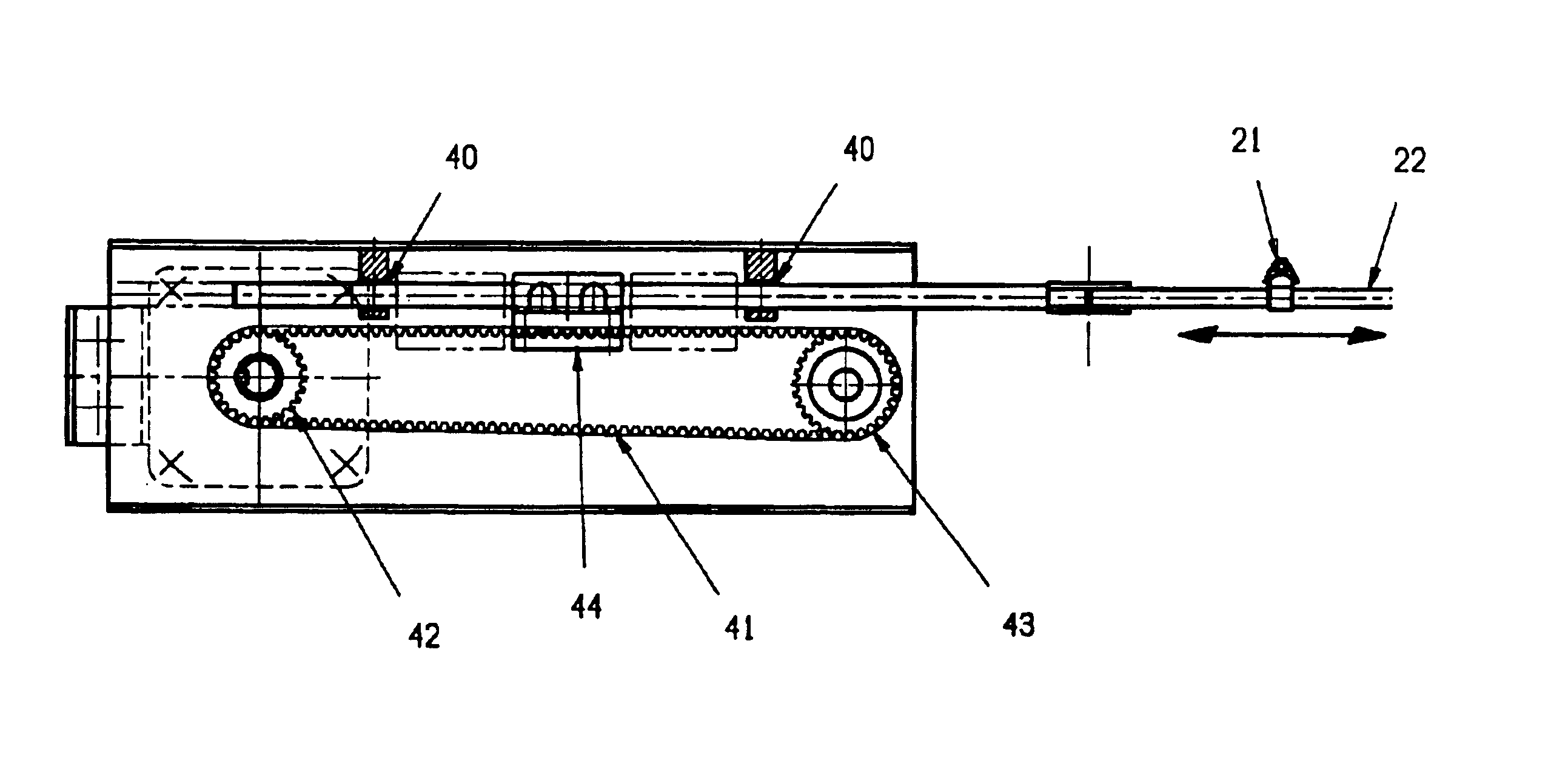
Thread-guiding device for collecting spun yarns on bobbins, particularly for open-end spinning frames, constituted by a common thread-guiding rod which carries the thread-guides for the spinning units, driven in alternate movement in front of the bobbins being formed by the motion of a driving means controlled in turn by a motor capable of alternate rotation and controlled by the control unit of the spinning frame in its alternate clockwise / counterclockwise movement as regards instantaneous speed, amplitude of angular excursion, angular coordinates of the ends of its travel.

Description

FIELD OF INVENTION[0001]The present invention relates to collecting spun yarn produced or worked by textile machines to be wound on bobbins.BACKGROUND OF INVENTION[0002]In the industrial production of spun yarns it is common practice for them to be collected on an idle tube carried by a bobbin-carrying arm, which rests on a rotating driving roller and takes up the spun yarn coming from a feed element to wind it onto itself. The bobbin is thus formed by pulling and winding the spun yarn on its surface, it being drawn in rotation by the roller underneath on which the bobbin being formed rests. This practice allows the spun yarn to be wound at a substantially constant linear speed, irrespective of the increasing dimensions of the bobbin and depending only on the rotation speed of said driving roller. The spun yarn is wound in spirals onto the rotating bobbin as the pick-up unit is provided with a thread-guiding device which distributes the spun yarn on the outer surface of the bobbin w...

Claims


Application Information

Patent Timeline
Patent Type & Authority Patents(United States)
IPC IPC(8): B65H54/28B65H54/38B65H57/26B65H54/02B65H57/00
CPCB65H54/2818B65H54/385B65H57/006B65H57/24B65H2701/31B65H2403/52B65H2515/12B65H2555/24
Inventor BADIALI, ROBERTOCOLUSSI, VITTORIOVIGNUT, FRANCO SIEGA
Owner SAVIO MACCHINE TESSILI
Learn More