
Adjustable back tension rope release

Inactive Publication Date: 2005-05-24
SUMMERS GREGORY E
View PDF13 Cites 32 Cited by
  • Summary
  • Abstract
  • Description
  • Claims
  • Application Information

AI Technical Summary

Benefits of technology

[0005]This invention relates to a triggerless back tension rope release that provides additional freedom of movement during draw by incorporating, in one exemplary embodiment, a two-link release head assembly, each link (a forward link and an intermediate link) freely pivotable about respective pivots relative to each other and to the release handle. The sear, formed with a rope loop hook, is pivotably mounted on the forward link while a D-shaped pawl is adjustably fixed for movement with the intermediate link. This arrangement allows the archer to draw the bow, with the handle portion of the release assuming various positions and angles throughout the draw cycle, relative to the release head assembly but without affecting the relationship between the pawl and the sear. A locking mechanism is provided that includes mutually perpendicular drive and locking rods that can be actuated through a lever in the handle portion to lock the intermediate link of the release head in any desired position, but leaving the forward link that supports the sear free to swivel relative to its respective pivot axis, with its arcuate range limited by the position of the intermediate link. In this locked position, the handle, intermediate link and pawl will move together relative to the sear. The arrow can then be released by the conventional movement or flexing of the hand and / or wrist that causes the pawl to move to a position that releases the sear for movement, i.e., the sear edge moves over the pawl edge, that concurrently causes the rope loop to disengage from the sear hook and the arrow to fire, under the influence of tension in the bow string.
[0006]In another arrangement, the “pawl” has a substantially triangular shape with radiused corners where the sides of the triangle meet the base. In this case, the sear edge is arranged to engage one of the sides of the triangle adjacent the base, and to be released as it passes across one of the radiused corners when the archer moves the release and the pawl sufficiently to allow the rear edge to clear the pawl. A pair of set screws are arranged to engage the two sides of the triangle, thus permitting very fine adjustments to the pawl vis-a-vis the sear. Since the pawl is pivotally mounted through a center portion thereof, the set screws engaging the side of the triangle work in opposed directions, i.e., tightening of one requires loosening of the other and vice versa.
[0007]The above described release head assembly and locking mechanism allows the archer to find the optimum draw position before locking the intermediate link, eliminating or at least significantly reducing any potential premature firing of the arrow.
[0008]It is another feature of the invention to fix the rope loop ends at a location on the forward link of the release head assembly that is closely adjacent and forward of the pivot pin of the sear, and more particularly, closely adjacent the rope loop hook on the sear. This arrangement insures that the release rope travels from its connection holes in the forward link in a straight line around the bow string and back to the sear hook, where the distance between the release rope lengths at the bow string is equal to or greater than the distance between the release rope lengths at the rope connection holes in the sear and the rope loop hook on the sear. In other words, the distance between the rope release lengths at the sear is substantially equal to or less than the diameter of the bow string. This insures that the bow string is maintained accurately in the exact same position of the release rope “cradle,” not allowing the bow string to slide or move to a varying positions, thereby maintaining a consistent amount of back tension travel to release the shot.

Problems solved by technology

This kind of twist or torque applied to the release rope can result in reduced arrow speed and accuracy.
Increased sensitivity, however, increases the potential for accidental premature firing and / or the possibility of injury to the archer as is or her arm snaps back toward the face.

Method used


Image

  • Adjustable back tension rope release
  • Adjustable back tension rope release
  • Adjustable back tension rope release

Examples


Embodiment Construction

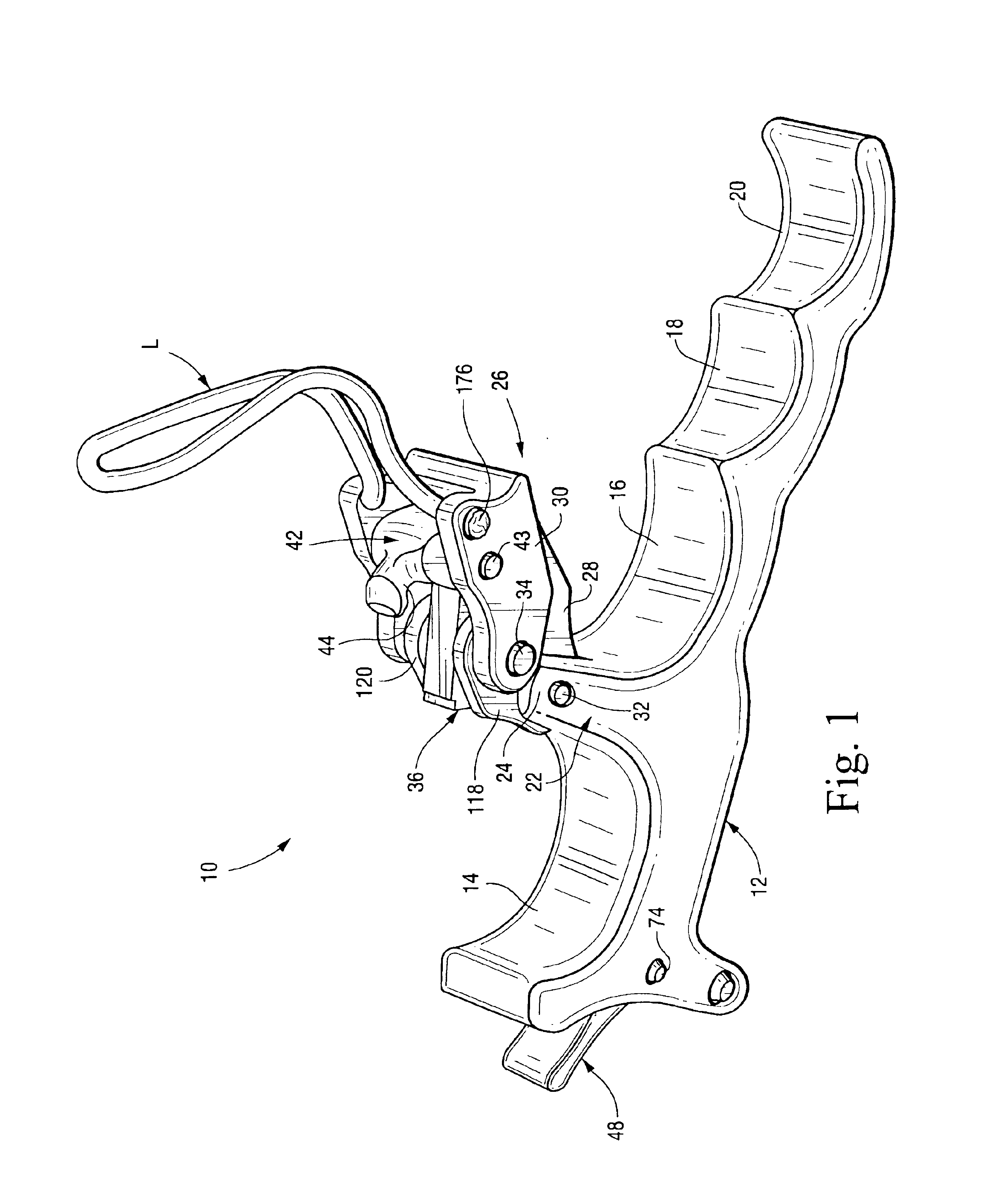
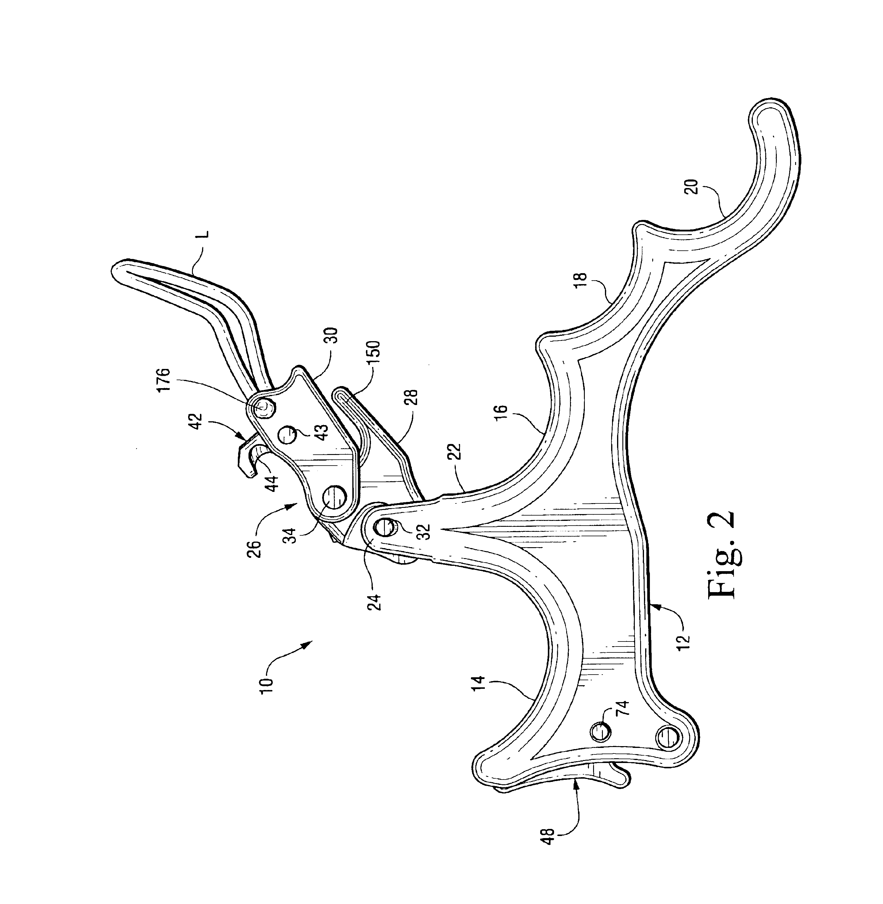
[0053]With reference initially to FIGS. 1-4, the release 10 generally includes a handle portion 12 formed with finger grooves 14, 16, 18 and 20 for four-fingered engagement. The number of grooves may be varied as desired, however, depending on personal preference. For example, the release could also have two or three finger grooves. A post 22 extends generally perpendicularly away from the handle portion 12, between the first and second finger grooves 14 and 16, terminating at a fork including a pair of substantially identical laterally spaced bosses 23, 24.

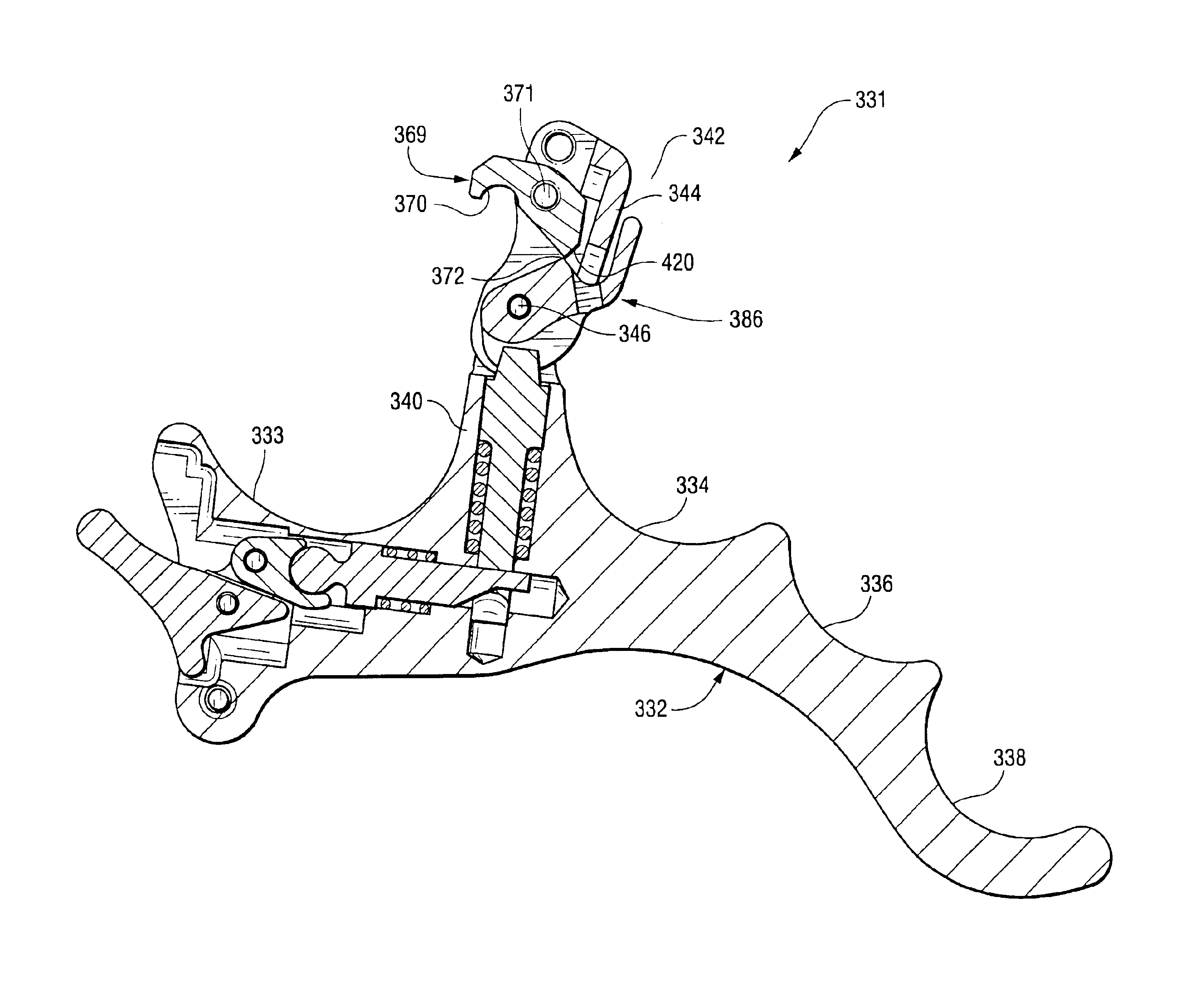
[0054]A release head assembly 26 includes intermediate and forward release links 28 and 30, respectively. The intermediate link 28 is pivotally mounted to the post 22 via pin 32, while the forward release link 30 is pivotally mounted to the intermediate release link 28 via pin 34. A pawl 36 (FIGS. 1, 3, 16 and 17) in the form of a truncated or generally D-shaped disk, is adjustably fixed to the intermediate link 28, also via pin ...


PUM


Abstract

A triggerless back tension release for use with a bow string comprising a handle; a release head assembly including a rope loop and a first component pivotally mounted relative to a portion of the handle, the first component carrying a sear element having a sear edge and a hook adapted for receiving the rope loop; a locking rod located in the handle portion and actuated by a lever in the handle portion to engage and lock a second component of the release head assembly relative to the handle portion, the second component arranged to interact with the sear edge and to release the sear element and thereby release the bow string upon movement of the handle portion.

Description

[0001]This is a continuation-in-part of application Ser. No. 10 / 173,747 filed Jun. 19, 2002, now U.S. Pat. No. 6,647,976 continuation-in-part of application Ser. No. 09 / 925,023 filed Aug. 9, 2001, now U.S. Pat. No. 6,584,966, the entire contents of which are incorporated herein by reference. This invention relates to a bow string release and, more specifically, to a triggerless back-tension type release.BACKGROUND OF THE INVENTION[0002]Various release devices are utilized in archery to assist the archer in pulling a bow string to a fully drawn position and then releasing the bow string to fire, an arrow. Many of these devices include mechanical grippers that engage the bow string directly, or that engage nock elements mounted on the bow string. Other devices use rope looped about the bow string as the release mechanism with or without a mechanical trigger. In release devices of the latter kind, the looped rope is often subject to a twisting action as the archer draws the bow string ...

Claims


Application Information

Patent Timeline
IPC IPC(8): F41B5/00F41B5/18
CPCF41B5/1469
Inventor SUMMERS, GREGORY E.RENTZ, MARC T.SUMMERS, RANDY V.
Owner SUMMERS GREGORY E
Learn More