Orthopedic traction device

a traction device and orthopedic technology, applied in the field of orthopedic equipment, can solve the problems of affecting the operation of the operating table, requiring very sturdy operating table, and requiring heavy weight, so as to minimize friction between the moving components, facilitate installation, and accurate indication of the traction force

Inactive Publication Date: 2005-05-24
COMPOSITE MFG
View PDF10 Cites 23 Cited by
  • Summary
  • Abstract
  • Description
  • Claims
  • Application Information

AI Technical Summary

Benefits of technology

[0006]The principal and secondary objects of this invention are to provide an orthopedic traction apparatus that can be conveniently installed on a surgery table, treatment jig, or hospital bed and provide an accurate indication of the traction force while avoiding the use of weights and other heavy and cumbersome components. These and other val

Problems solved by technology

This prior art equipment is bulky, heavy, and cumbersome to use.
The handling of weights can

Method used


Image

  • Orthopedic traction device
  • Orthopedic traction device
  • Orthopedic traction device

Examples


Embodiment Construction

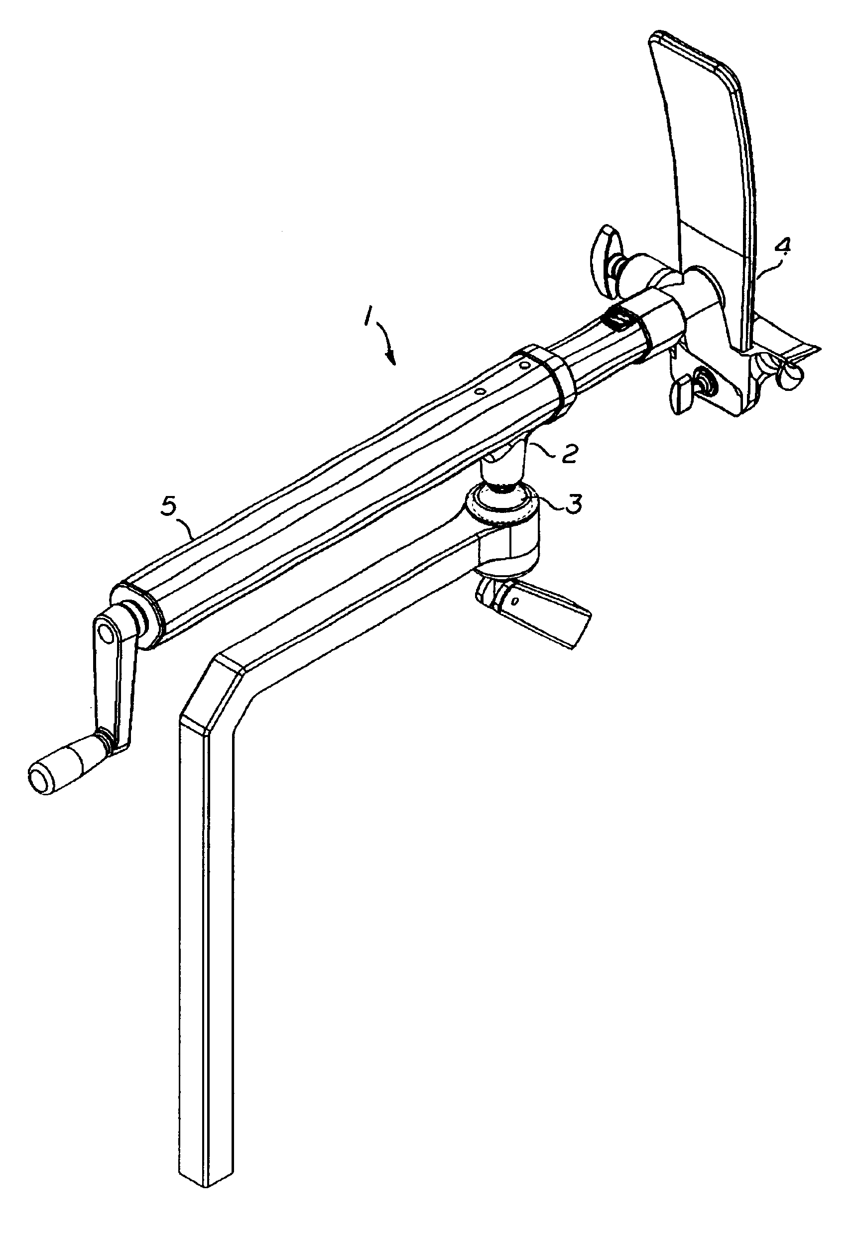
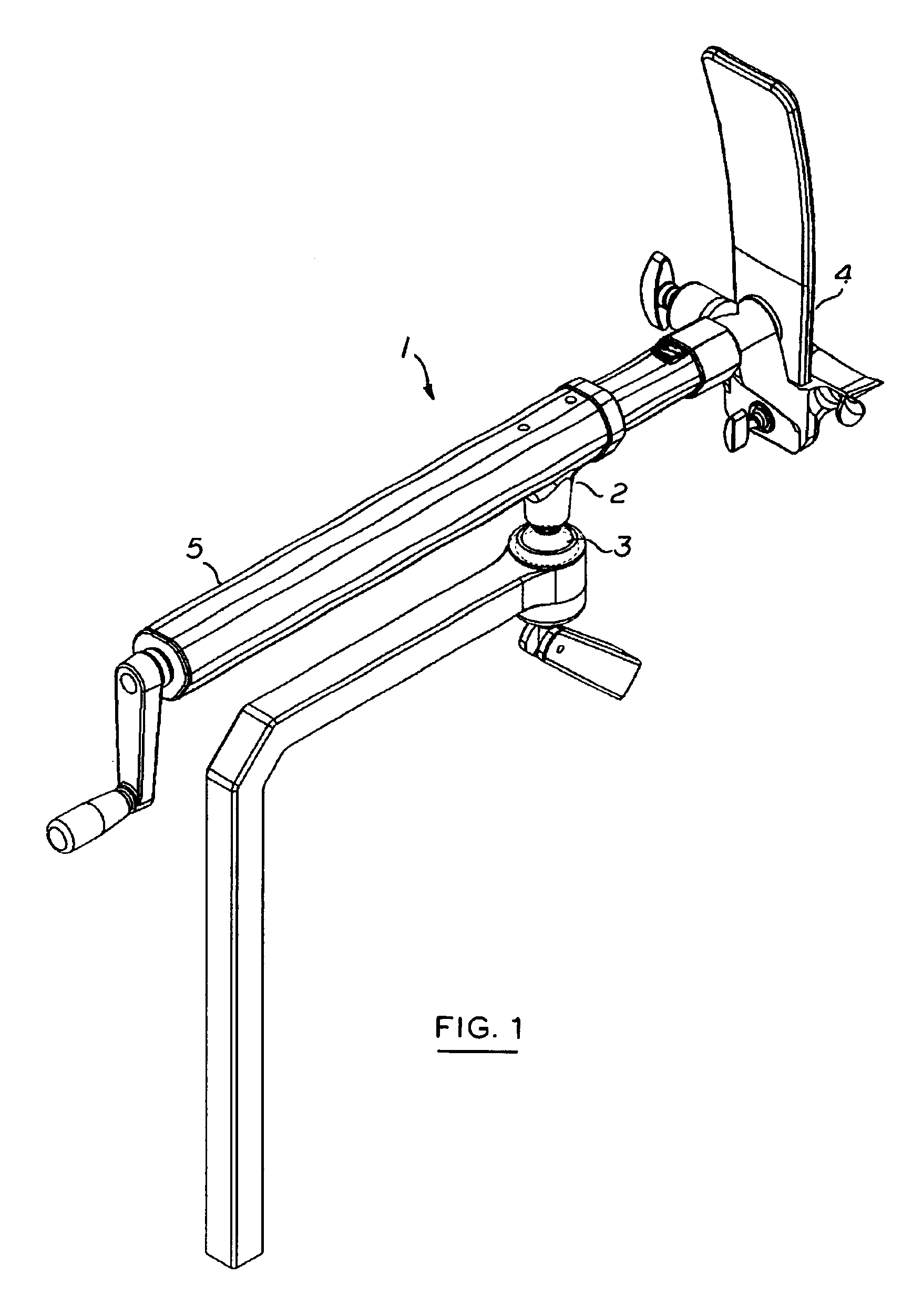
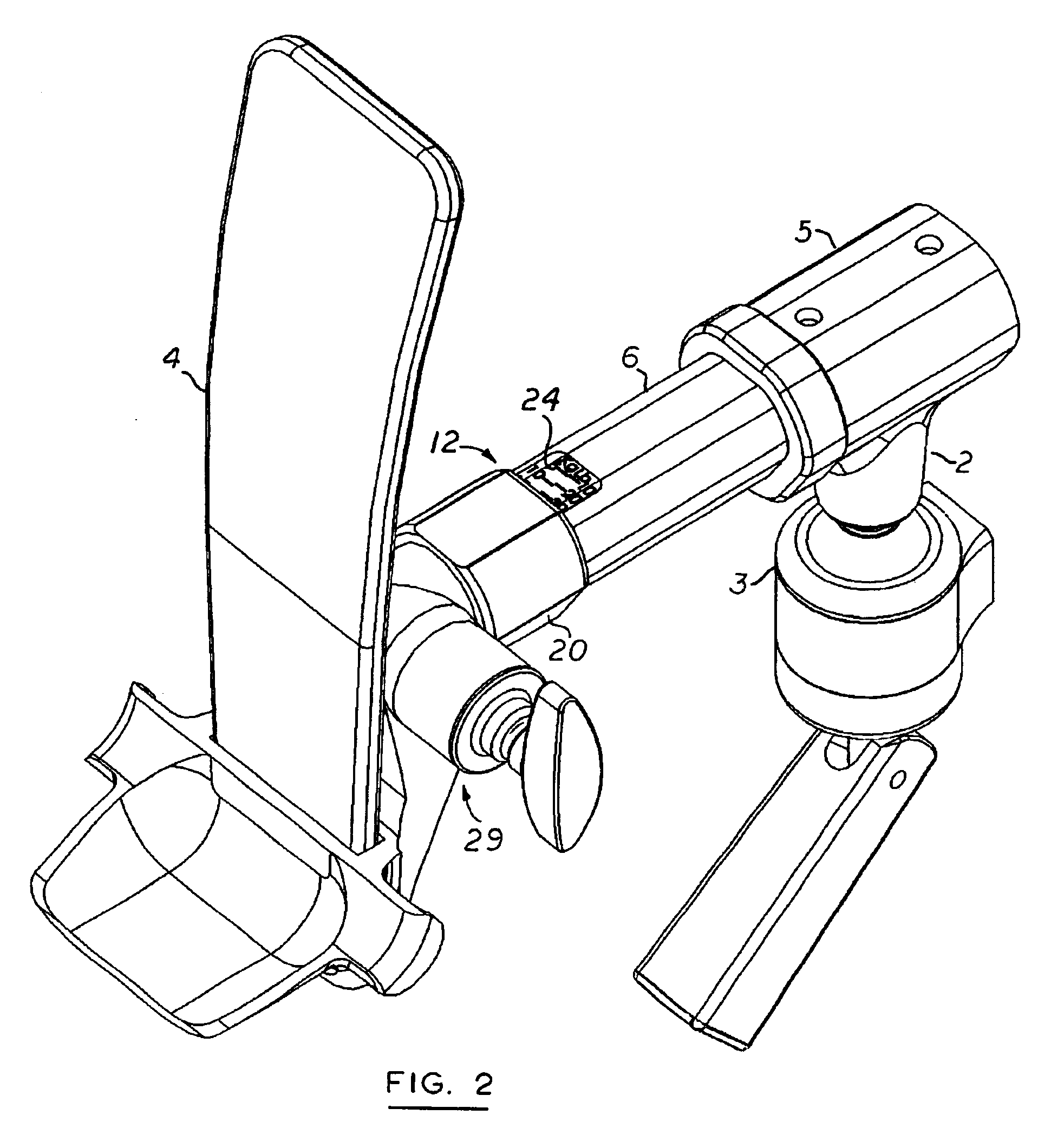
[0014]Referring now to the drawing, there is shown an orthopedic apparatus 1 for applying traction to a patient's body part and more specifically to a patient's arm or leg. The apparatus preferably anchored to an operating table, bed, treatment jig or other stationary structure fixedly supporing the pateint. The attachment is by means of a multi-positonable coupling comprising a bracket 2 terminated by a ball-and-socket assembly 3. At the distal end of the apparatus a a stirrup fixture 4 is configured to securely attach to a boot worn by the patient. Typically, a pair of such traction apparatus would be used to operate on both legs in order to balance the tension applied to the patient's pelvis. The traction mechanism is contained into a first tubular housing 5 secured to the coupling bracket 2 and a more distal second tubular housing 6 concentrically and telescopically engaged into the first.

[0015]The stirrup fixture 4 is mounted at the distal end of a spline shaft 7 slidingly enga...


PUM


Abstract

An orthopedic traction apparatus includes in coaxial arrangement, a first tubular member anchored to a operating table or other stationary structure supporting a patient, and a second tubular member telescopically moving within the first one. A hand-crank and jack-screw mechanism is used to vary the position of the second member in relation to the first member. A tensiometer is provided at the distal end of the second member proximate a fixture adapted for attachment to a part of a patient's body. The tensiometer is based on a compressible, calibrated coil spring and is provided with a vernier scale for convenient and precise adjustment of the traction force. Alternately, the tensiometer uses a load-cell driving a digital read-out.

Description

FIELD OF THE INVENTION[0001]This invention relates to orthopedic equipment and more particularly to mechanisms used by orthopedic surgeons and physical therapists to apply traction to a limb or other part of the body.BACKGROUND OF THE INVENTION[0002]Orthopedic surgeons and physical therapists often use traction to treat traumas affecting a part of body's bone structure.[0003]For instance, traction may be applied to a leg in order to realign a broken femur bringing the two fractioned interfaces together so that they can be rejoined. Traction may also be used to lengthen a limb that has atrophied as a result of a degenerative muscular disorder such as poliomyelitis. In such a case, the femur is sewed into two sections and traction is applied to the leg to bring the two severed sections into close proximity and letting the natural regrowth of the bone feel the traction-induced gap.[0004]Traction is typically applied over a long period of time with progressive increase of the traction f...

Claims


Application Information

Patent Timeline
IPC IPC(8): A61F5/04
CPCA61F5/04
Inventor MALCOLM, ROGER J.SALTER, TIM M.KELLY, ROB D.SANDERS, WARD L.PETERSON, BRYAN P.
Owner COMPOSITE MFG
Why Eureka
Try Eureka