Stratified scavenging carburetor

a carburetor and scavenging technology, applied in the field of carburetor, can solve the problems of difficulty in starting and warming up the engine, inability to operate the engine, etc., and achieve the effect of facilitating the starting of the engin

Active Publication Date: 2005-05-24
NIPPON WALBRO KK
View PDF37 Cites 40 Cited by
  • Summary
  • Abstract
  • Description
  • Claims
  • Application Information

AI Technical Summary

Benefits of technology

[0007]Some objects, features and advantages of stratified scavenging carburetors as set forth herein include providing a carburetor that delivers to an engine a desired fuel and air mixture over a wide range of operating conditions from idle to wide open throttle engine operation, and starting and warming up of an engine, enables separate control of a throttle valve during a choke assisted start of an engine, automatically sets a throttle valve to a start position upon closing a choke valve, provides an enriched fuel and air mixture to an engine to facilitate starting the engine, permits automatic return of a choke valve from its closed position to its open position, provides a compact carburetor that includes a scavenging air passage, air valve, choke valve and throttle valve, prevents delivery of scavenging air to an engine during a choke assisted start of the engine, enables relative movement between the throttle valve and air valve during at least a portion of the throttle valve movement, is durable, reliable and of economic manufacture and assembly.

Problems solved by technology

In this stratified scavenging arrangement, the fuel to air mixture ratio within a combustion chamber of the engine can become too lean with the addition of air from the air passage at idle and other low speed and low load engine operating conditions resulting in unstable engine operation under these conditions.
Air flow through the air passage at this time can make the fuel and air mixture leaner than desired resulting in difficulty starting and warming up the engine.

Method used


Image

  • Stratified scavenging carburetor
  • Stratified scavenging carburetor
  • Stratified scavenging carburetor

Examples


Embodiment Construction

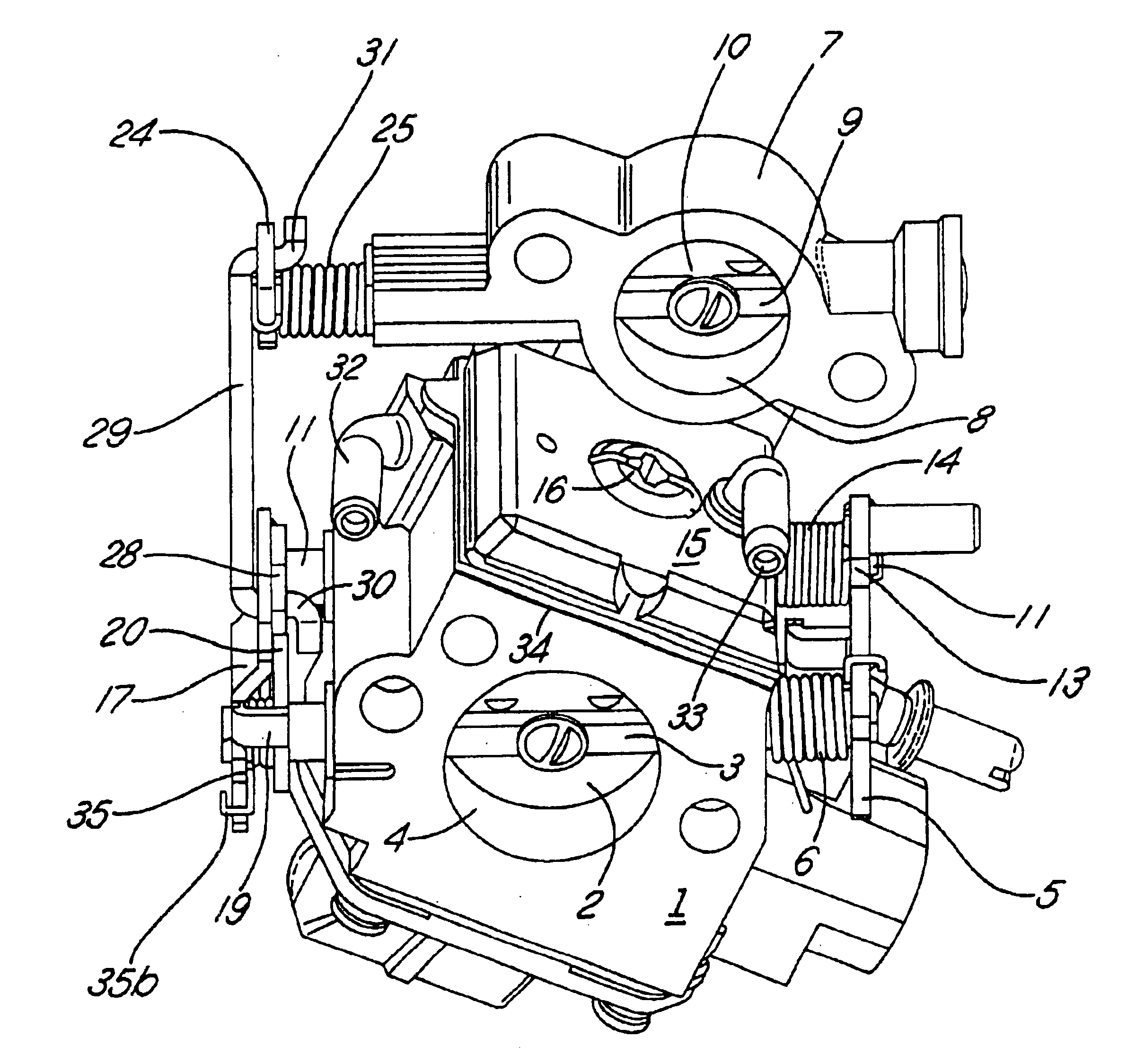
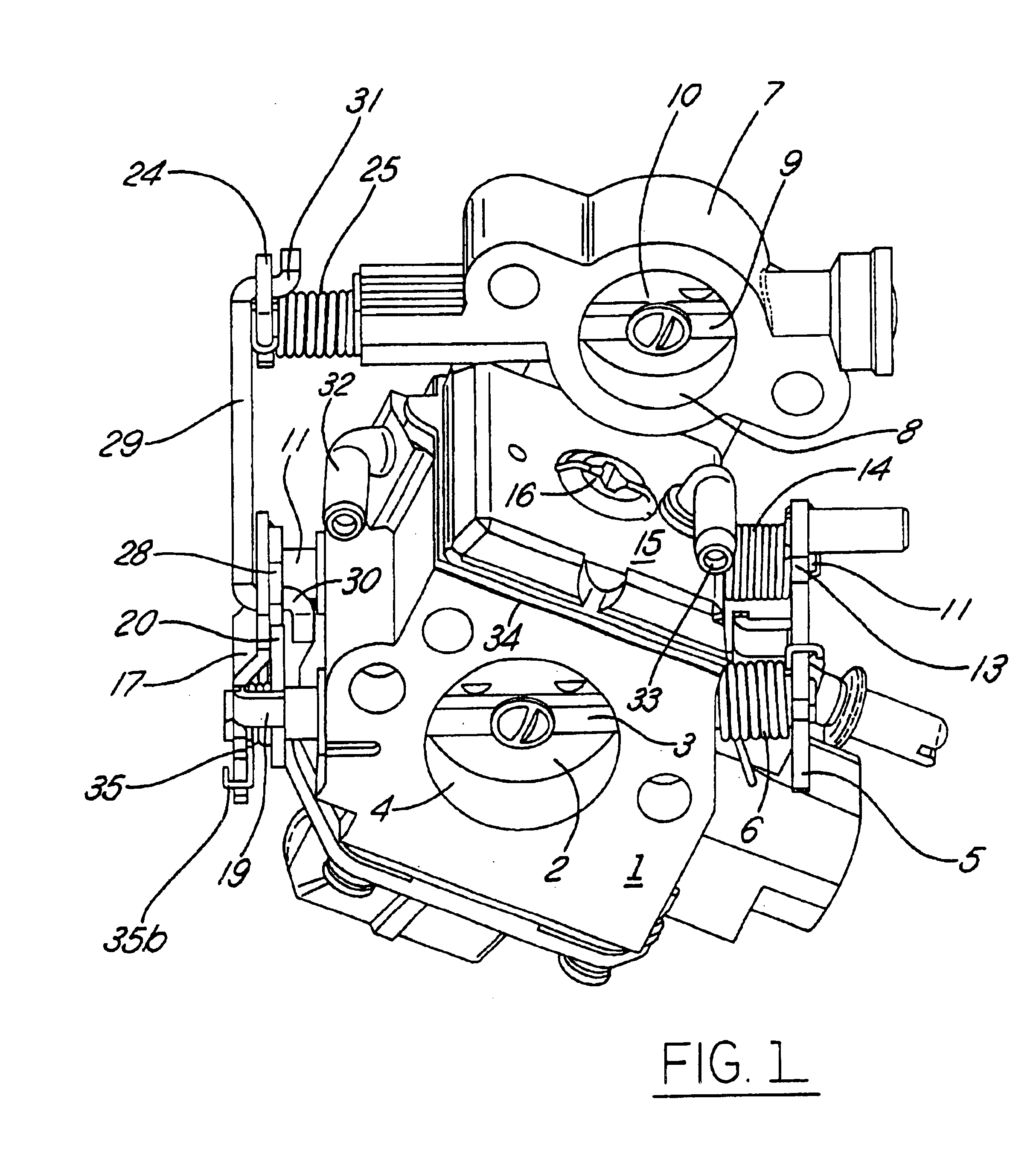
[0023]As shown in FIG. 1, a carburetor body 1 includes an air intake and fuel mixing passage 4 extending through the body 1 and a pump cover 15 carried by the body and securing a diaphragm 34 between the cover 15 and body 1 by a bolt 16. When pressure pulsations of a crankcase chamber of the engine are introduced into a pulsation pressure chamber on the upper side of the diaphragm 34 through a pipe 33, fuel in a fuel tank (not shown) is taken into a pump chamber on the lower side of the diaphragm 34 from a fuel inlet pipe 32, and is supplied to a fuel metering chamber of a substantially constant pressure fuel supply mechanism of the carburetor. Fuel in the fuel metering chamber is preferably supplied to the air intake passage 4 via a low-speed fuel nozzle and a high-speed fuel nozzle for delivery to the engine in a fuel and air mixture. Hence, fuel and air is mixed in the air intake passage which can also be called a fuel and air mixing passage.

[0024]A butterfly-type throttle valve ...


PUM

PropertyMeasurementUnit
displacementaaaaaaaaaa
rotationaaaaaaaaaa
timeaaaaaaaaaa

Abstract

A stratified scavenging carburetor with a lost motion coupling permits limited relative movement of a throttle valve relative to an air valve so that initial opening of the throttle valve off idle does not open the air valve to avoid diluting with scavenging air the fuel and air mixture delivered to an engine. Rotation of the throttle valve beyond a predetermined amount from idle causes a corresponding opening of the air valve to provide scavenging air to the engine. Closing a choke valve engages a lock lever with the throttle valve to move the throttle valve off idle to a start position without opening the air valve. In another embodiment, closing the choke valve prevents the air valve from opening even if the throttle valve is moved beyond where the throttle valve would cause the air valve to open if the choke valve were open. Thus, a richer than normal fuel and air mixture can be supplied to the engine during a choke-assisted start and warm-up of the engine.

Description

REFERENCE TO RELATED APPLICATION[0001]Applicants claim priority of Japanese patent application, Ser. No. 2002-344,389, filed Nov. 27, 2002.FIELD OF THE INVENTION[0002]The present invention relates generally to a carburetor and more particularly to a stratified scavenging carburetor for controlling delivery of a fuel and air mixture and scavenging air to a stratified scavenging 2-stroke engine.BACKGROUND OF THE INVENTION[0003]In a 2-stroke engine, stratified scavenging arrangements have been used to reduce or prevent the blow-through or loss of fuel through exhaust ports at the time of a fuel and air mixture entering the combustion chamber. Some such arrangements use an air passage that is separate from a fuel and air mixture passage, and scavenging is done with a layer of air provided from the air passage at the outset of scavenging, after which scavenging is done with a fuel and air mixture, and at the same time, new air is taken into a crankcase chamber.[0004]In this stratified sc...

Claims


Application Information

Patent Timeline
Patent Type & Authority Patents(United States)
IPC IPC(8): F02M1/00F02M23/03F02M7/12F02M23/00F02M7/00F02M1/02F02D9/02F02B25/00F02B25/22F02B75/02F02M19/00
CPCF02M7/12F02M23/03F02M1/02F02B25/22F02B2075/025F02D2009/0279Y10S261/01Y02T10/146Y02T10/12
Inventor SUZUKI, MASAONAGATA, HIROSHIKOJIMA, TETSUJI
Owner NIPPON WALBRO KK
Why Eureka
Try Eureka