Dirt collecting system for a floor care appliance

a technology for collecting system and floor care appliances, applied in the direction of auxillary pretreatment, cleaning filter means, separation processes, etc., can solve the problems of general drop in cleaning performance, and achieve the effect of improving sustained filtration performance and being easy to empty

Inactive Publication Date: 2005-05-24
HEALTHY GAIN INVESTMENTS
View PDF15 Cites 96 Cited by
  • Summary
  • Abstract
  • Description
  • Claims
  • Application Information

AI Technical Summary

Benefits of technology

The technical effect of this patent is that it describes an improvement to a dirt collection system for a vacuum cleaner. This upgrade has several benefits including better long-term filtering performance, easier emptying (no more bags needed), and effective prevention of larger dirt parts from coming back into the machine during operation. These improvements make the cleaning process faster, efficient, and overall more user-friendly.

Problems solved by technology

The technical problem addressed in this patent text is the need for a bagless floor care appliance that maintains cleaner performance even as the dirt collecting container becomes filled with debris.

Method used


Image

  • Dirt collecting system for a floor care appliance
  • Dirt collecting system for a floor care appliance
  • Dirt collecting system for a floor care appliance

Examples


Embodiment Construction

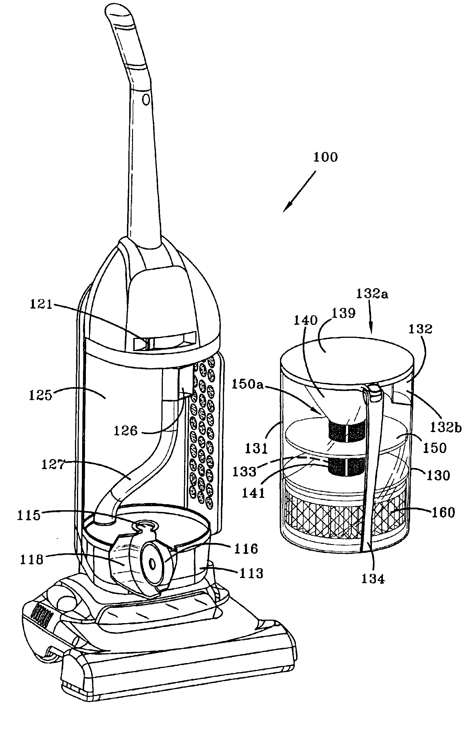
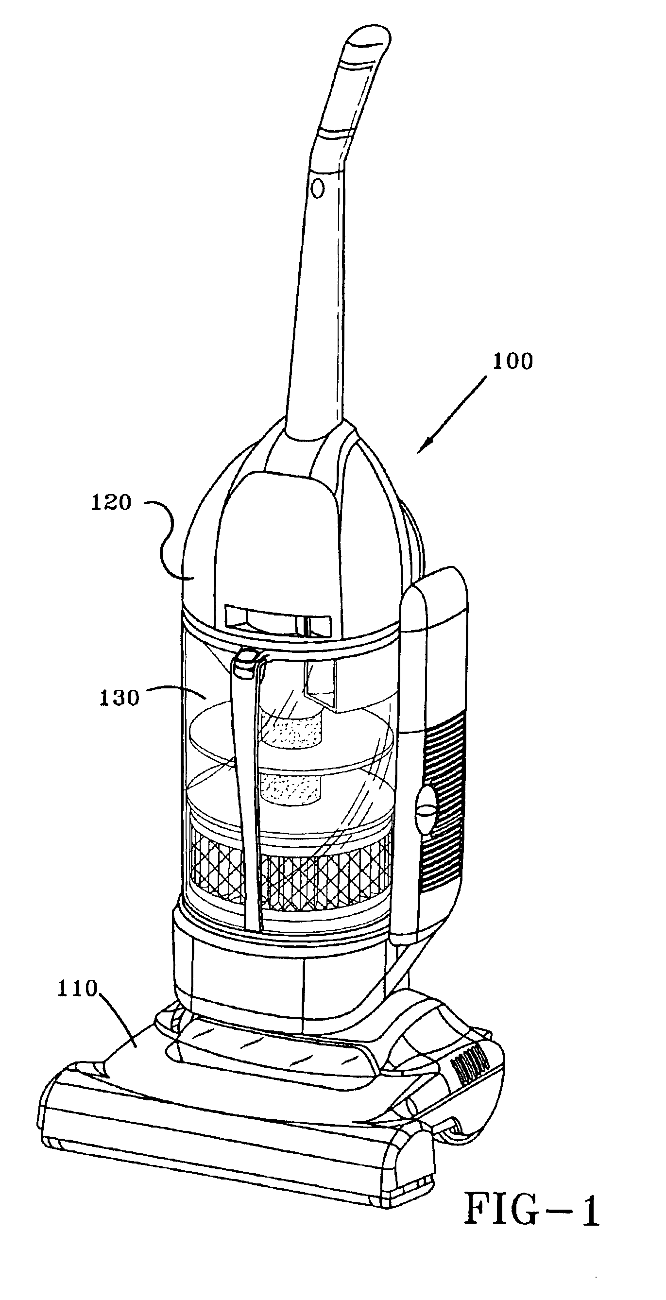
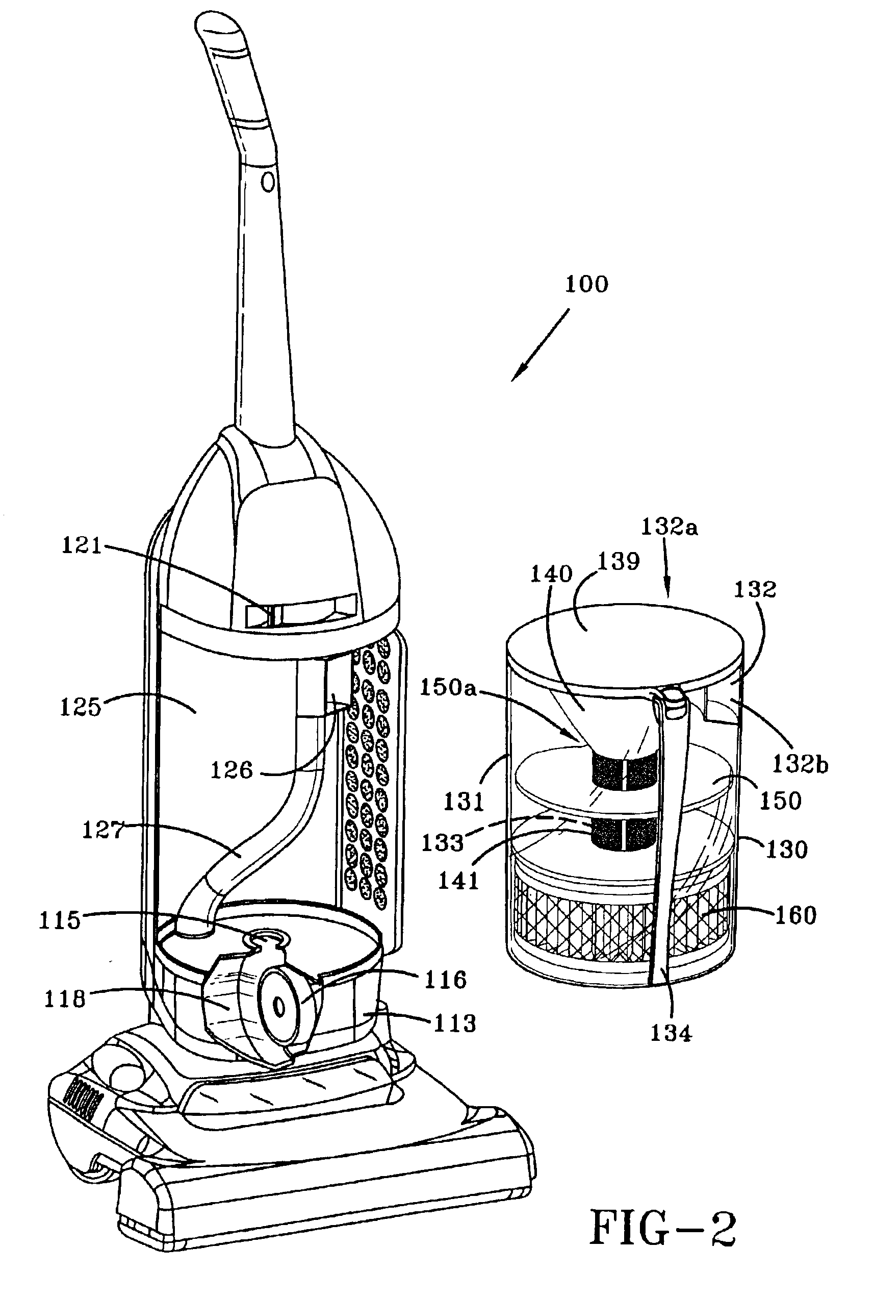
[0031]A vacuum cleaner incorporating the preferred embodiment of the present dirt collecting system is shown in FIGS. 1-9 and is indicated generally at 100. Vacuum cleaner 100 includes a vacuum cleaner housing 120 pivotally connected to a suction nozzle or vacuum cleaner foot 110. The foot 110 is typical being formed with a bottom nozzle opening (not shown) which opens towards a floor surface. One or more rotary agitators (not shown) may be positioned within one or more agitator chambers (not shown) which communicates with the bottom nozzle opening. The agitator(s) rotate for loosening dirt from the floor surface before being removed by suction from the suction nozzle 110. A dirt collecting system 130 is positioned in housing 120 for separating and collecting dirt particles from a dirt laden airstream from the suction nozzle 110. The dirt laden airstream is generated by a suction motor 116 (FIG. 2) which may be located in the foot 110 or housing 120.

[0032]The dirt collecting system ...


PUM

PropertyMeasurementUnit
Distanceaaaaaaaaaa
Circumferenceaaaaaaaaaa
Proximity effectaaaaaaaaaa

Abstract

A dirt collecting system for a vacuum cleaner includes a dirt cup formed from a cylindrical sidewall having a disc shaped member separating the dirt cup into an upper portion and a lower portion. The dirty airstream flows past the disc shaped member from the upper portion to the lower portion through a small gap between the outer periphery of the disc shaped member and the sidewall of the dirt cup. The disc shaped member is supported on a centrally located conduit which has apertured walls located both above and below the disc shaped member. The apertured walls allows the airstream to flow into the conduit for further filtering or exiting the dirt cup. The apertured wall located above the disc shaped member improves sustained performance by enabling the airstream to continue to flow through the dirt cup as the lower portion of the dirt cup fills with large dirt particles and the apertured wall located beneath the disc shaped member becomes increasingly restricted. In the various embodiments of the invention, the airstream is directed through the conduit to a fine particle filter located in a compartment at the bottom of the dirt cup, at the top of the dirt cup or into filter sock located at the upper end of the dirt cup. Alternately, the fine particle filter may be located in a separate container located above or below the dirt container.

Description


Claims


Application Information

Patent Timeline
Owner HEALTHY GAIN INVESTMENTS
Why Eureka
Try Eureka