Fastener strip with discrete magnetically attractable area, and method and apparatus of making same

a magnetic attractable area and fastener technology, applied in the field of touch fastening devices, can solve the problems of waste of process, major prior art of the previous paragraph, and magnetically attractable particles

Inactive Publication Date: 2005-05-24
YKK CORP
View PDF38 Cites 40 Cited by
  • Summary
  • Abstract
  • Description
  • Claims
  • Application Information

AI Technical Summary

Benefits of technology

[0064]Further, on the extruding die, a pair of extruding openings are formed on the upper and the lower positions along the rotational direction of the die wheel. In order to extrude the molten synthetic resin material, in which the magnetically attractable particles are mixed, into the magnetically attractable body molding cavity from the upper extruding opening, the upper extruding opening has a shape so as to continuously and specifically fill the magnetically attractable body molding cavity with molten synthetic resin. On the other hand, the lower extruding opening has a shape for extruding the molten synthetic resin specifically into the fastener strip molding cavity. By using this fastener strip manufacturing apparatus, it is possible to manufacture a fastener strip having the magnetically attr

Problems solved by technology

The prior art of the previous paragraph has a major disadvantage, however, in that the magnetically attractable particles are mixed into the resin that forms the entire hook and base layer of the fastener strip, and/or the entire substrate layer if a substrate layer is used.
This process is wasteful, because it uses more magnetically attractable particles than might otherwise be needed.
To the extent that magnetically attractable particles in the resin can affect other properties of the fastener strip, it can also degrade perf

Method used


Image

  • Fastener strip with discrete magnetically attractable area, and method and apparatus of making same
  • Fastener strip with discrete magnetically attractable area, and method and apparatus of making same
  • Fastener strip with discrete magnetically attractable area, and method and apparatus of making same

Examples


Embodiment Construction

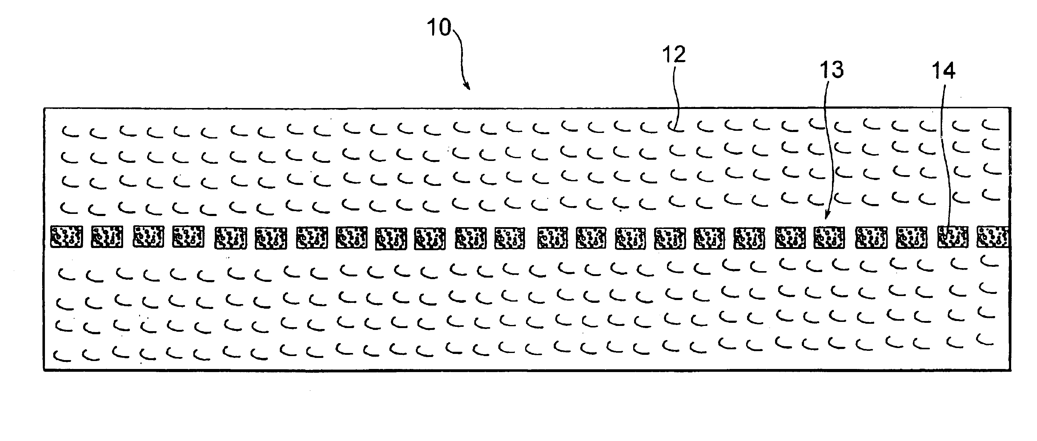
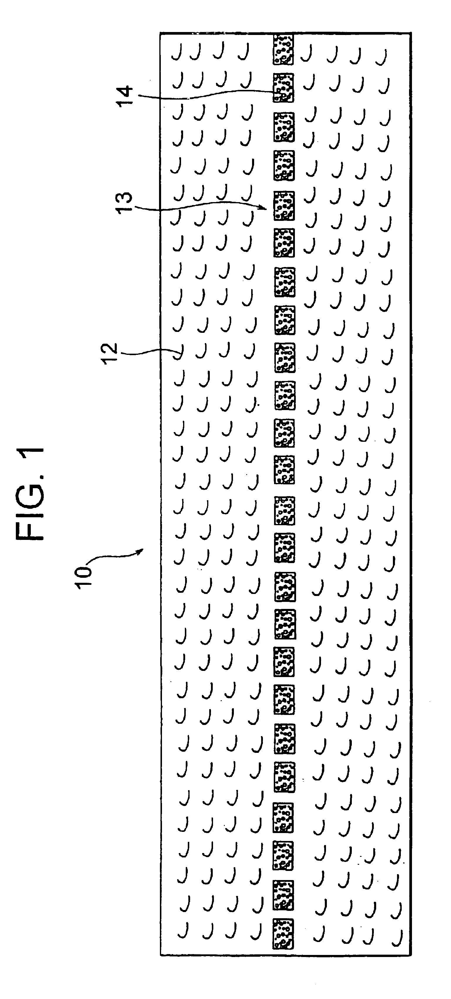
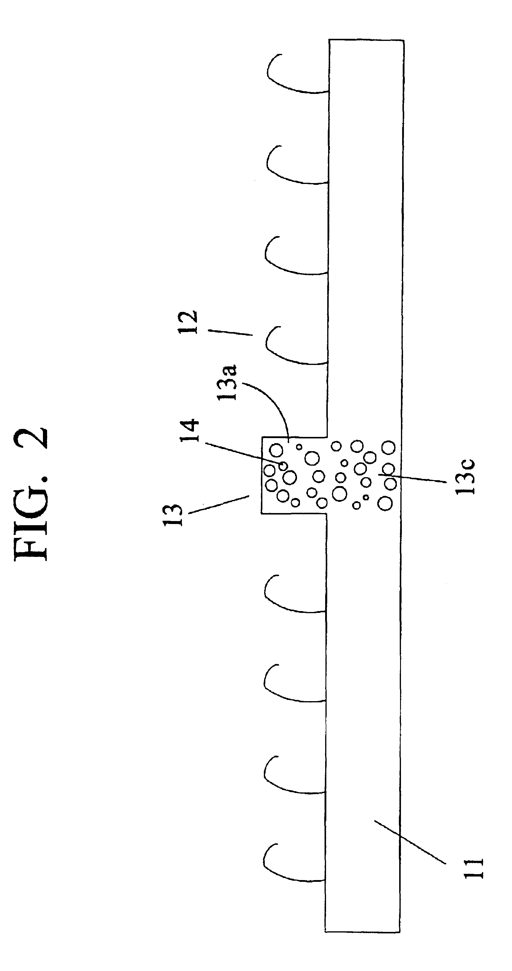
[0104]A list of reference numerals, which are used in the drawings, is as follows:[0105]10: fastener strip[0106]11: base[0107]12: fastening element (hook piece)[0108]13: magnetically attractable body[0109]13a: protrusion[0110]13b: valley portion[0111]13c: base material portion[0112]14: magnetically attractable particle[0113]15: wall[0114]16: barrier to prevent intrusion of molding material[0115]16a: vertical sealing member[0116]17: foam resin material[0117]18: laminate layer[0118]19: coating film[0119]20: metal wire[0120]21: magnetically attractable band material[0121]22: long magnetically attractable material[0122]24: resin[0123]25: magnetically attractable resin[0124]26: line[0125]30: mold[0126]30b: lower portion of mold[0127]31: magnet[0128]35: extruder[0129]35a: primary noble[0130]36: die wheel[0131]36a: hook-shaped cavity[0132]36b: magnetically attractable body molding cavity[0133]37: supplementary particle reservoir[0134]37a: supplementary particle channel[0135]37b: supplement...


PUM

PropertyMeasurementUnit
Widthaaaaaaaaaa
Circumferenceaaaaaaaaaa

Abstract

The present invention provides a fastener strip having magnetically attractable particles which are not located across the entire volume of the strip, but rather are incorporated in a discrete, distinct area of the strip. The fastener strip has a base and many hook pieces which rise from a fastening surface of the base. One embodiment has a magnetically attractable body in a row which rises from the surface of the base and is located along a substantially center line of the fastener strip. The magnetically attractable particles are incorporated in the magnetically attractable body and a part of the base located below the magnetically attractable body, and the magnetically attractable particles are not dispersed across the whole area of the base. A method of manufacturing such a strip is also described here.

Description

CROSS-REFERENCES TO RELATED APPLICATIONS[0001]This application is a divisional of Ser. No. 09 / 971,512 filed Oct. 5, 2001, which is a continuation-in-part of U.S. patent application Ser. No. 09 / 848,977 filed May 4, 2001 now abandoned.BACKGROUND[0002]1. Field of the Invention[0003]This invention is in the area of touch fastening devices, specifically a fastener strip with magnetically attractable bodies that are incorporated into discrete, individually distinct areas of the strip—rather than being distributed generally throughout the volume of the strip. A process for manufacturing such a strip is also described.[0004]2. Description of the Related Art[0005]It can be appreciated that a seat for a vehicle or the like is configured by attaching a superficial skin member on a surface of a cushion body. In order that a person sitting on the seat can maintain a seated posture and not tire even if he or she is sitting for a long time, a structure having a concave form is employed. In a seat ...

Claims


Application Information

Patent Timeline
IPC IPC(8): A44B18/00B29C47/10B29C47/32B32B3/06B29C47/12B32B33/00B32B5/18B60N3/04B29C48/05B29C48/35
CPCA44B18/0049A44B18/0076B29C47/0021B29C47/32B32B3/06B32B5/18B32B33/00B60N3/046B60N3/048A44B18/0061Y10T428/24008A44D2203/00B29C47/003B29C47/0033B29K2105/0005B29K2105/16B29K2995/0008B29L2031/729B29C47/1027Y10S428/90Y10T428/24182Y10T24/27Y10T428/24174Y10T428/24017B29C48/288B29C48/08B29C48/12B29C48/13B29C48/35B29C48/05
Inventor FUJISAWA, NOBUOGRAHAM, CRAIG JAYMINATO, TSUYOSHIMURASAKI, RYUICHIAKENO, MITSURU
Owner YKK CORP
Why Eureka
Try Eureka