
Float glass making process and float glass making equipment

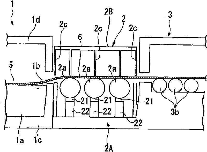
A float glass, manufacturing method technology, applied in glass manufacturing equipment, glass transportation equipment, manufacturing tools and other directions, can solve problems such as glass ribbon pollution

Active Publication Date: 2010-06-23
ASAHI GLASS CO LTD
View PDF2 Cites 15 Cited by
  • Summary
  • Abstract
  • Description
  • Claims
  • Application Information

AI Technical Summary

Problems solved by technology

Next, the adhered molten metal is brought out from the molten metal bath by reattaching to the lower surface of the glass ribbon, and adheres to the outer peripheral surface of the lift-up roll to form oxide protrusions or corrode the outer circumference of the lift-up roll in the same manner as above. Contamination or defects may occur on the glass ribbon due to recesses or microscopic defects

Method used


Image

  • Float glass making process and float glass making equipment
  • Float glass making process and float glass making equipment
  • Float glass making process and float glass making equipment

Examples


Embodiment

[0075] (experiment 1)

[0076] use Figure 9 In the shown experimental apparatus for forming a carbon film, a carbon film was formed on a quartz glass plate (sample) 105 as a roll constituent material of a lift-up roll, and various evaluations were performed on the formed carbon film.

[0077] right Figure 9 The experimental apparatus shown will be described, and the experimental apparatus 100 is mainly composed of a tubular electric furnace 103 provided with a heater 102 on the outer periphery of a tubular reaction vessel 101 . A sample stand 104 made of a heat-resistant material is installed inside the reaction vessel 101 , and a quartz glass plate 105 on which a carbon film is to be formed is placed on the sample stand 104 . In addition, a supply tube 106 made of quartz glass for supplying an introduction gas containing a carbon-containing gas is provided in the reaction vessel 101 . The gas supply nozzle 106 a located at the end of the supply pipe 106 is provided near ...


PUM

PropertyMeasurementUnit
thicknessaaaaaaaaaa

Abstract

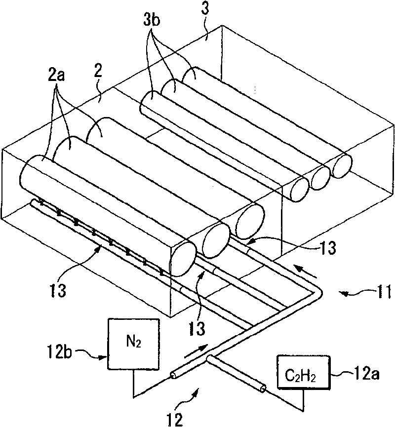
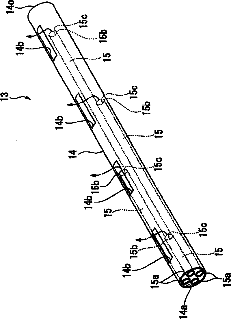
A float glass making process and float glass making equipment devised to prevent any occurrence of stain or flaw. There is disclosed a float glass making process through continuously feeding a molten glass onto a horizontal surface of molten metal bath wherein a molten metal is accommodated to thereby form a glass ribbon, drawing up the glass ribbon from the bath surface and delivering the same by means of multiple delivery rolls to a slow cooling furnace, characterized in that the forming, drawing up and delivery of the glass ribbon are carried out under the condition of having a carbon film formed on the surface of the delivery rolls.

Description

technical field [0001] The invention relates to a float glass manufacturing method and float glass manufacturing equipment. Background technique [0002] In the method for producing float glass, first, molten glass is continuously supplied to the horizontal bath surface of a bath containing molten metal to form a glass ribbon, and then the glass ribbon is lifted from the outlet of the molten metal bath and pulled out of the molten metal bath. The glass ribbon is formed into a target thickness by a tensile force that lifts the glass ribbon from the outlet of the bath. Then, the glass ribbon is conveyed by conveying rollers (also referred to as lift rollers), is sent to a slow cooling furnace, and is slowly cooled while being conveyed in the slow cooling furnace. Thereafter, the glass ribbon is cut into predetermined lengths to manufacture plate-shaped float glass. [0003] In the above-mentioned float glass manufacturing method (hereinafter also referred to as the float met...

Claims


Application Information

Patent Timeline
Patent Type & Authority Applications(China)
IPC IPC(8): C03B18/02C03B18/16C03B35/16
CPCC03B35/181C03B25/08C03B18/16C03B25/025
Inventor 谷井史朗
Owner ASAHI GLASS CO LTD
Learn More