Grommet for a wire harness

a wire harness and grommet technology, applied in the field of grommets, can solve the problems of little room for loading supplementary parts, loss of flexibility of the tubular portion b>3/b>, and breakage of the sealing, so as to achieve the effect of reducing the force of pushing, reducing the force of pulling, and greatly enhancing the holding power of the grommets

Active Publication Date: 2005-05-24
SUMITOMO WIRING SYST LTD
View PDF13 Cites 42 Cited by
  • Summary
  • Abstract
  • Description
  • Claims
  • Application Information

AI Technical Summary

Benefits of technology

[0052]In such structure, when the grommet is inserted into the through hole of the body panel, only the outermost face of the ribs is placed into contact with the rim of the through hole. In this manner, the contact surface, and contact resistance, is reduced, and less pushing force is needed. As already mentioned, the end faces (tips) of the funnel ribs in this embodiment extend around the external face of the first tubular portion. As a result, when the wire harness is installed in the body panel hole with the grommet and submitted to a force tending to pull it off, the first tubular portion shifts towards the funnel-shaped portion. Then, the end faces of the funn

Problems solved by technology

However, as the water-trapping agent 5 fills the space between the electrical cables W and then hardens, the tubular portion 3 loses its flexibility.
However, as the number of parts placed in a vehicle has increased greatly in recent years, there is little room for loading supplementary parts.
Typically, when the wire harness exiting from the grommet is turned at a sharp angle, deformations are caused in the funnel-shaped portion i

Method used


Image

  • Grommet for a wire harness
  • Grommet for a wire harness
  • Grommet for a wire harness

Examples


second embodiment

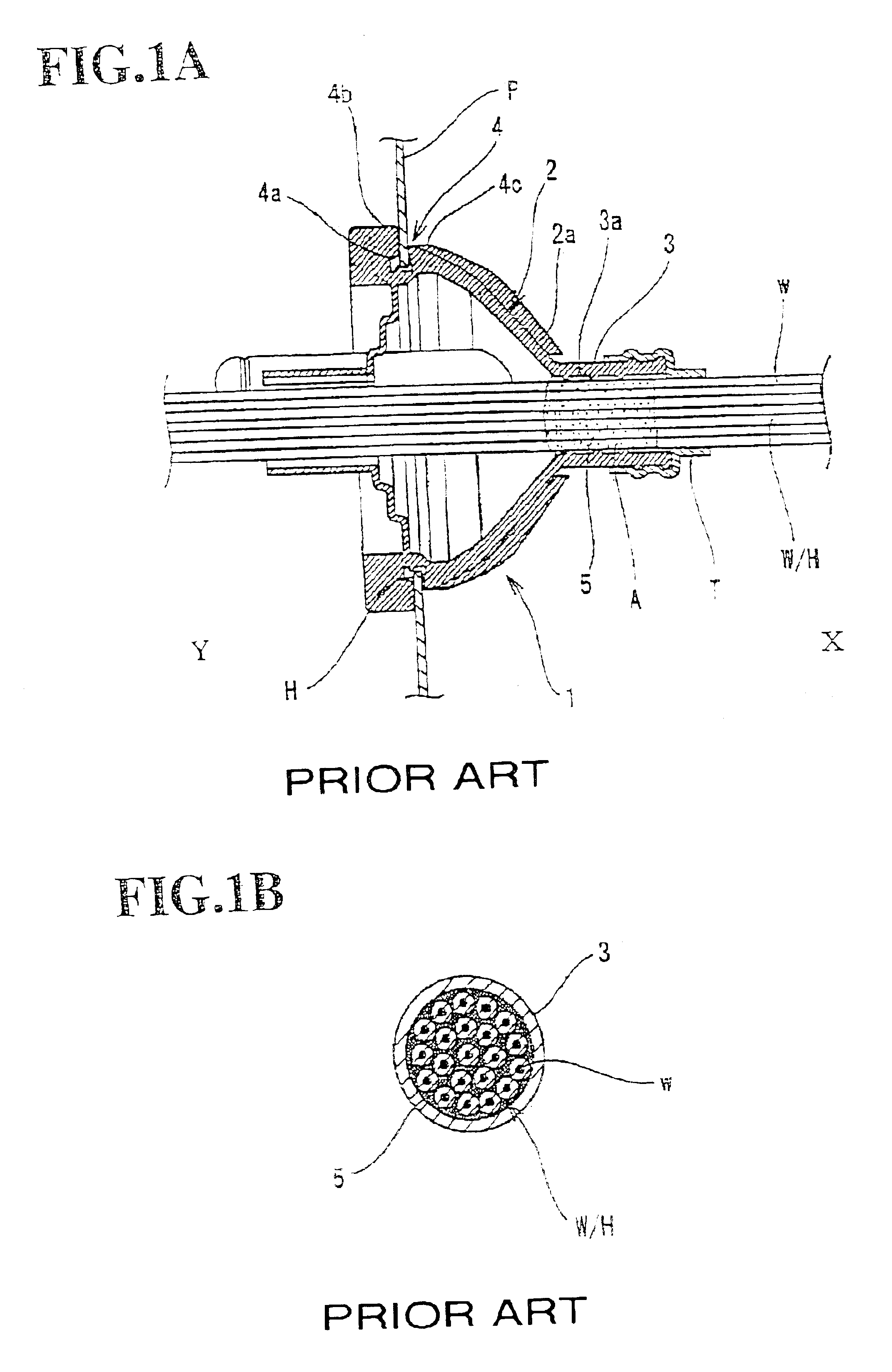
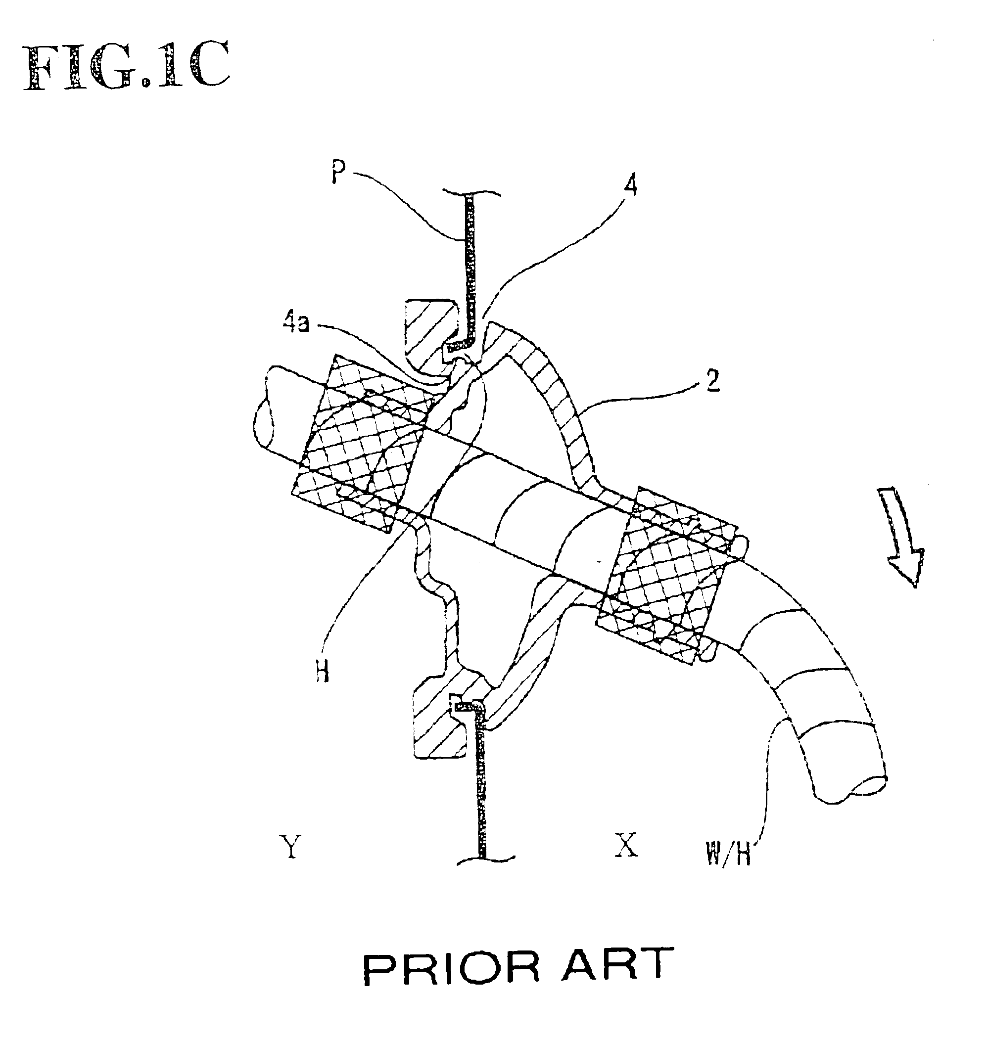
[0101]In the invention, the axial length of the grommet 10 is reduced. Accordingly, the funnel-shaped portion 12 projects less into the passenger compartment X, and the tubular portion 11 atop is not away from the body panel P. The wire harness contained in the tubular portion 11 can thus be wired readily alongside the body panel P.

[0102]The wire harness thus acquires a greater freedom for wiring in the passenger compartment.

[0103]The external circular face of the tubular extension 18 is tapered from the portion linking to the tubular portion 11 towards the end section 18c of the extended tubular portion 18. In other words, the tightening force of the extended tubular portion 18 increases towards the tubular portion 11 along axis Z. This prevents the water-trapping zone from moving towards the tubular portion 11. For instance, a water-trapping agent S, e.g. silicone, is painted around the respective electrical cables of the wire harness, forming thus a water-trapping zone in about 2...

third embodiment

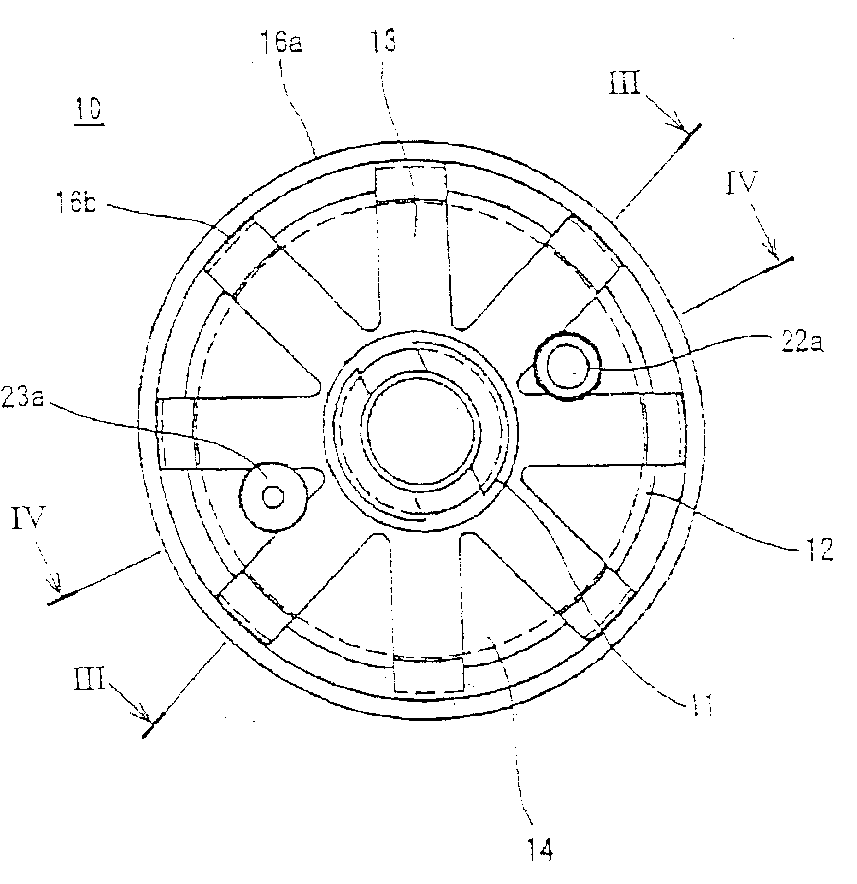
[0111]In a third embodiment, the end sections 13a of the funnel ribs 13 are inclined so as to form the circular space V around the first tubular portion 11 and, in the side sectional view, these end sections 13a extend parallel to axis Z of the tubular portion over its external face.

[0112]Further, an internal circular recess 12X is formed in the inner face of the funnel-shaped portion 12, at a position opposing the circular space V. The funnel-shaped portion 12 thus forms a circular joint section 25, at its narrowed end, which joins the funnel-shaped portion 12 to the tubular portion. The circular joint section 25 is made thin and is thus defined by the circular space V and the internal circular recess 12X.

[0113]By virtue of this configuration, the tubular portion 11 can be flexed easily against the funnel-shaped portion, and this flexion has no effect on the latter.

[0114]In other words, the tubular portion 11 can be flexed around the circular joint portion 25 independently from the...

fourth embodiment

[0116]In a fourth embodiment, the auxiliary tube 22 is used for passing a washer hose, and the auxiliary tube 23 is used for passing a hood (bonnet) wire. The letters “W” and “H”, respectively designating the washer hose and the hood wire, may be embossed at the flared end of the funnel-shaped portion 12, so as to avoid path errors.

[0117]As already mentioned, the closing face 20 shutting the flared end of the funnel-shaped portion 12 is made of a thin film and opened at its central area (i.e. harness aperture). The second tubular portion 21 is made of two arched channel members 21b and 21c (thus forming open paths therebetween), which protrude through the harness aperture. An auxiliary aperture 24 is formed in extension of each of the open passages, and the auxiliary tubes 22 and 23 are passed through the respective auxiliary apertures 24. The end sections 22b and 23b of the auxiliary tubes 22 and 23 form closed ends 22c and 23c, which are cut off along cutting lines 22d and 23d whe...


PUM


Abstract

The grommet having a longitudinal axis includes a funnel shaped portion having a flared end, a narrowed end and a conical wall with external and internal conical faces. The external conical face includes an external circular groove having a groove base. The grommet further includes a tubular portion extending outwardly from a circular joint section formed at the narrowed end of the funnel shaped portion. The grommet is configured to mount a wire harness for vehicles containing a water-trapping zone, and to be installed into a through-hole formed in a body panel of a vehicle. The funnel-shaped portion includes at least one device for improving the flexibility of and/or space availability for the wire harness to be mounted including an extended tubular portion to hold the water-trapping zone of the wire harness, a structural configuration allowing the length along the longitudinal axis of the funnel shaped portion to be reduced such that the wire harness can be wired substantially alongside the body panel, and a plurality of funnel ribs having closely arranged first end sections that form a circular space around the tubular portion.

Description

BACKGROUND OF THE INVENTION[0001]1. Field of the Invention[0002]The present invention relates to a grommet, in particular for mounting on a wire harness fitted in vehicles such as automobiles. More particularly, the invention relates to a “one-motion grommet” (or “one-way grommet”), which is installed by insertion into a through-hole of a vehicle body panel. The grommet of the present invention provides mechanical protection, as well as water and dust protection, for the wire harness at the insertion point of the through-hole.[0003]2. Description of Background Information[0004]It is already known to install a grommet on the wire harness leading from the engine compartment to the passenger compartment of an automobile. Such a grommet is mounted around the through-hole of the car-body panel / bulkhead. The car-body panel / bulkhead separates the passenger compartment from the engine compartment of an automobile. The grommet protects the wire harness passing through the through-hole and pr...

Claims


Application Information

Patent Timeline
IPC IPC(8): B60R16/02
CPCB60R16/0222Y10T16/05Y10T16/063
Inventor SAKATA, TSUTOMUUCHIDA, YOSHIMI
Owner SUMITOMO WIRING SYST LTD
Why Eureka
Try Eureka