Matrix display driver with energy recovery

Inactive Publication Date: 2005-05-24
KONINKLIJKE PHILIPS ELECTRONICS NV
View PDF4 Cites 12 Cited by
  • Summary
  • Abstract
  • Description
  • Claims
  • Application Information

AI Technical Summary

Benefits of technology

[0011]In the circuit in accordance with the invention, an extra switch circuit is connected in parallel with the inductor to keep the above-mentioned current in a loop which is as small as possible. Furthermore, the switch circuit has to withstand a lower voltage than the second switch and will have a lower impedance in a practical implementation. But most importantly, the two or three diodes are not within the loop. Even if a unidirectional switch circuit is required, only one instead of two or three diodes is in the loop. Thus, in the circuit in accordance with the invention, th

Problems solved by technology

Although the prior-art energy recovery circuit provides an efficient energy recovery, this circuit produces a considerable amount of Electro-Magnetic Interference (EMI).
In practice, the problem of the prior art is even more severe a

Method used


Image

  • Matrix display driver with energy recovery
  • Matrix display driver with energy recovery
  • Matrix display driver with energy recovery

Examples


Example

DETAILED DESCRIPTION OF THE DRAWING FIGURES

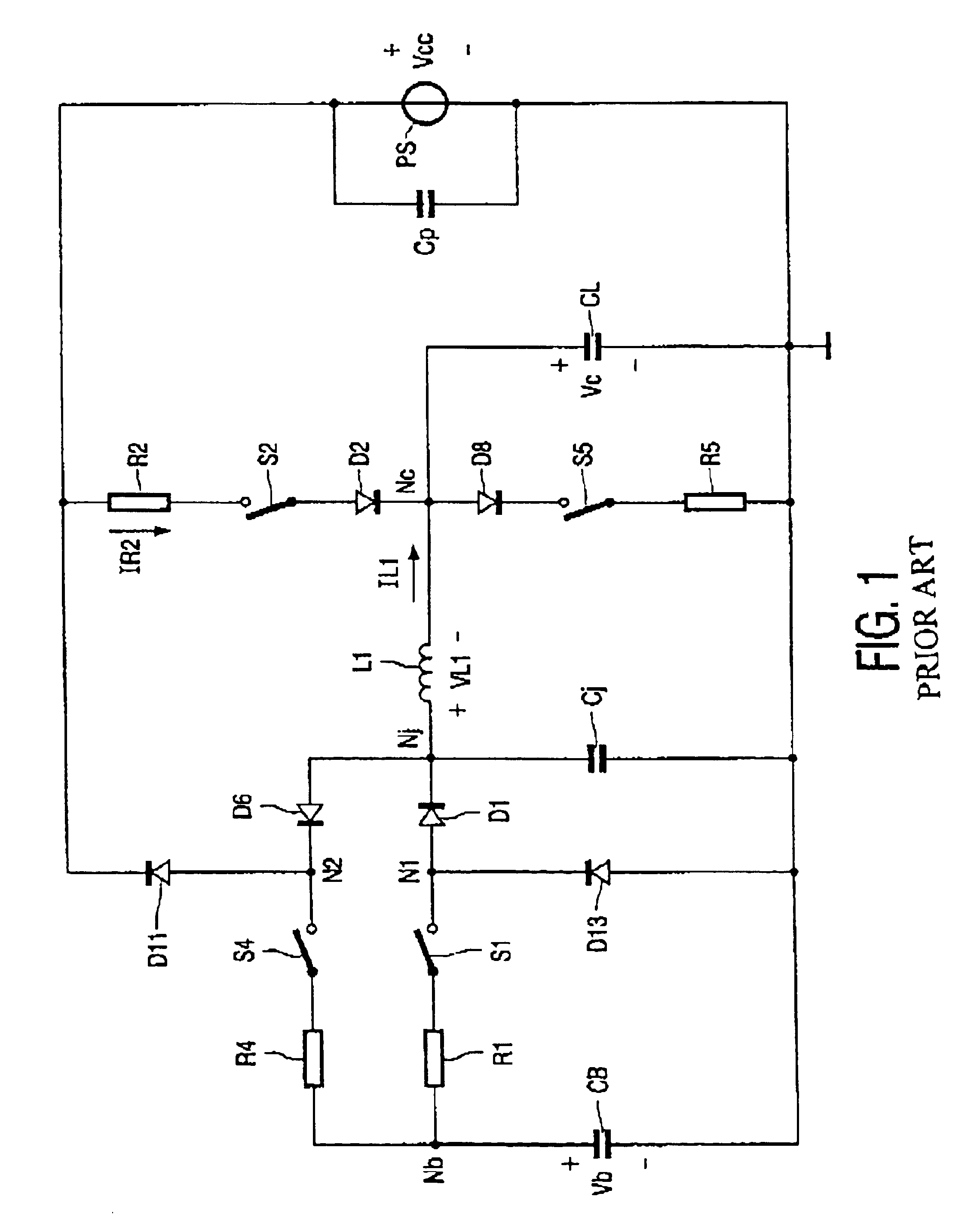
[0022]FIG. 1 is a detailed circuit diagram of a prior-art matrix display driver circuit with energy recovery.

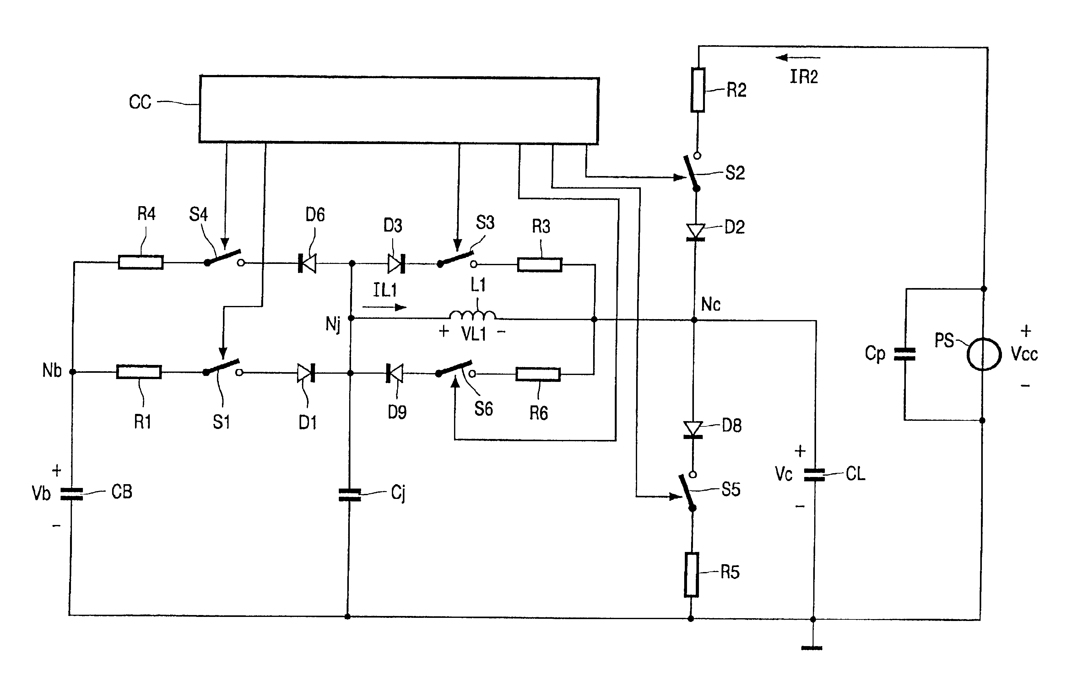
[0023]The driver circuit comprises a buffer capacitor CB arranged between a node Nb and ground. A series arrangement of an ideal switch S1 and a resistor R1 is connected between the node Nb and a node N1. A series arrangement of an ideal switch S4 and a resistor R4 is connected between the node Nb and a node N2. All series arrangements of an ideal switch and a corresponding resistor represent a practical switch (for example, a MOS-FET) with an on-resistance equal to the resistor value. The resonance inductor L1 is arranged between a node Nj and a node Nc. The current IL1 through the inductor is defined to flow from the node Nj to the node Nc. The voltage VL1 across the inductor is the voltage difference between the node Nj and the node Nc. The node Nj is connected to the node N1 via a diode D1, and to the node N2 via a diode D6. The ...


PUM


Abstract

In the matrix display drive circuit with an energy recovery inductor (L1), a switch circuit (S3, D3, S6, d9) is connected in parallel with the inductor (L1) to keep the inductor current (TL1) in a loop which is as small as possible, and to keep the voltage (VL1) across the inductor (L1) as low as possible. Consequently, the energy stored in the inductor is lower, and the EM1 caused by the parasitic resonance of the inductor (L1) with parasitic capacitances Cj will be significantly lower.

Description

TECHNICAL FIELD[0001]The invention relates to an energy recovery matrix display driver circuit, and a matrix display apparatus with such a driver circuit.BACKGROUND AND SUMMARY[0002]Alternating voltages are required between electrodes of matrix displays like LCDs, Plasma Display Panels (PDP), Plasma Addressed Liquid Crystal displays (PALC), and Electro-Luminescent panels (EL). Due to a capacitance present between the electrodes, and required steep slopes of the alternating voltage, relatively large charge or discharge currents are required to reverse the polarity of the voltage across the capacitance. To minimize the power dissipation during the polarity reversal, driver circuits which comprise an energy recovery circuit in which an external inductance forms a resonant circuit with the capacitance are known from EP-A-0548051 and EP-A-0704834. Both these prior arts disclose an energy recovery circuit for a PDP.[0003]A PDP may be driven in a sub-field mode wherein, during a field or a...

Claims


Application Information

Patent Timeline
IPC IPC(8): G09C3/00G09G3/28G09G3/20H04N5/66G09G3/296
CPCG09G3/2965G09G2330/06G09G3/20
Inventor MCCORMACK, JAMES JOSEPH ANTHONY
Owner KONINKLIJKE PHILIPS ELECTRONICS NV
Why Eureka
Try Eureka