Coding method, coding apparatus, decoding method and decoding apparatus using subsampling

Inactive Publication Date: 2005-05-24
MITSUBISHI ELECTRIC CORP
View PDF4 Cites 13 Cited by
  • Summary
  • Abstract
  • Description
  • Claims
  • Application Information

AI Technical Summary

Benefits of technology

[0015]Accordingly, a general object of the present invention is to provide a coding apparatus, a decoding apparatus, a coding method and a decoding apparatus and a decoding method in which the aforementioned disadvantages are eliminated.
[0016]Another and more specific object is to provide a coding apparatus, a decoding apparatus, a coding method and a decoding method capable of efficiently coding and decoding information with variable local characteristics.

Problems solved by technology

Since a determination as to whether subsampling should be performed is based on the magnitude of a prediction error, a relatively large increase in the threshold level for effective subsampling may result in insufficient reconstruction of characters and line drawings containing important information at the edges thereof.
Accordingly, two types of prediction, extrapolation prediction for basic pixels and interpolation prediction for the other pixels, are required, resulting in a disadvantage in that the construction of the apparatus becomes complex and the coding performance cannot be improved beyond a certain level.

Method used


Image

  • Coding method, coding apparatus, decoding method and decoding apparatus using subsampling
  • Coding method, coding apparatus, decoding method and decoding apparatus using subsampling
  • Coding method, coding apparatus, decoding method and decoding apparatus using subsampling

Examples


first embodiment

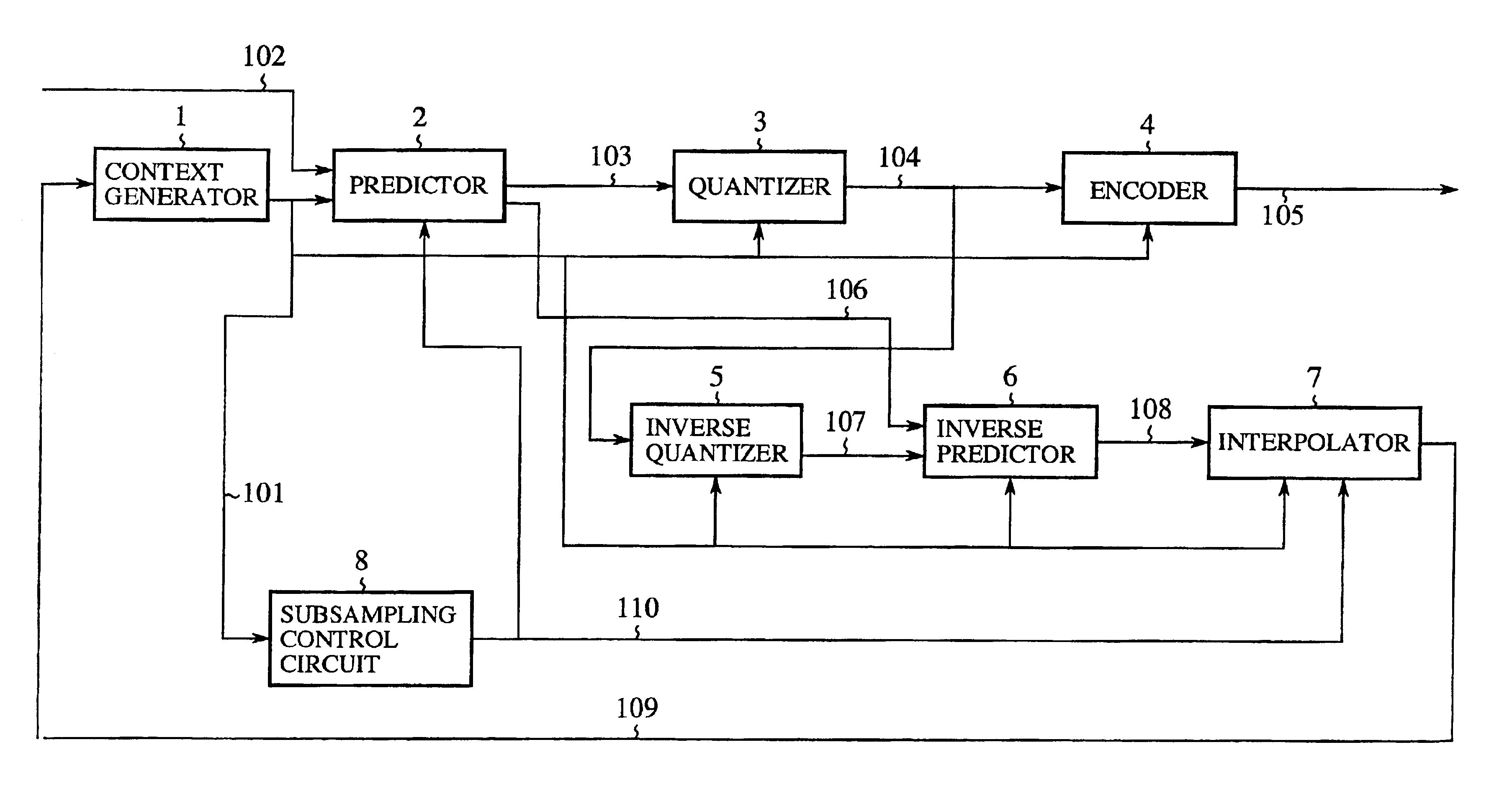
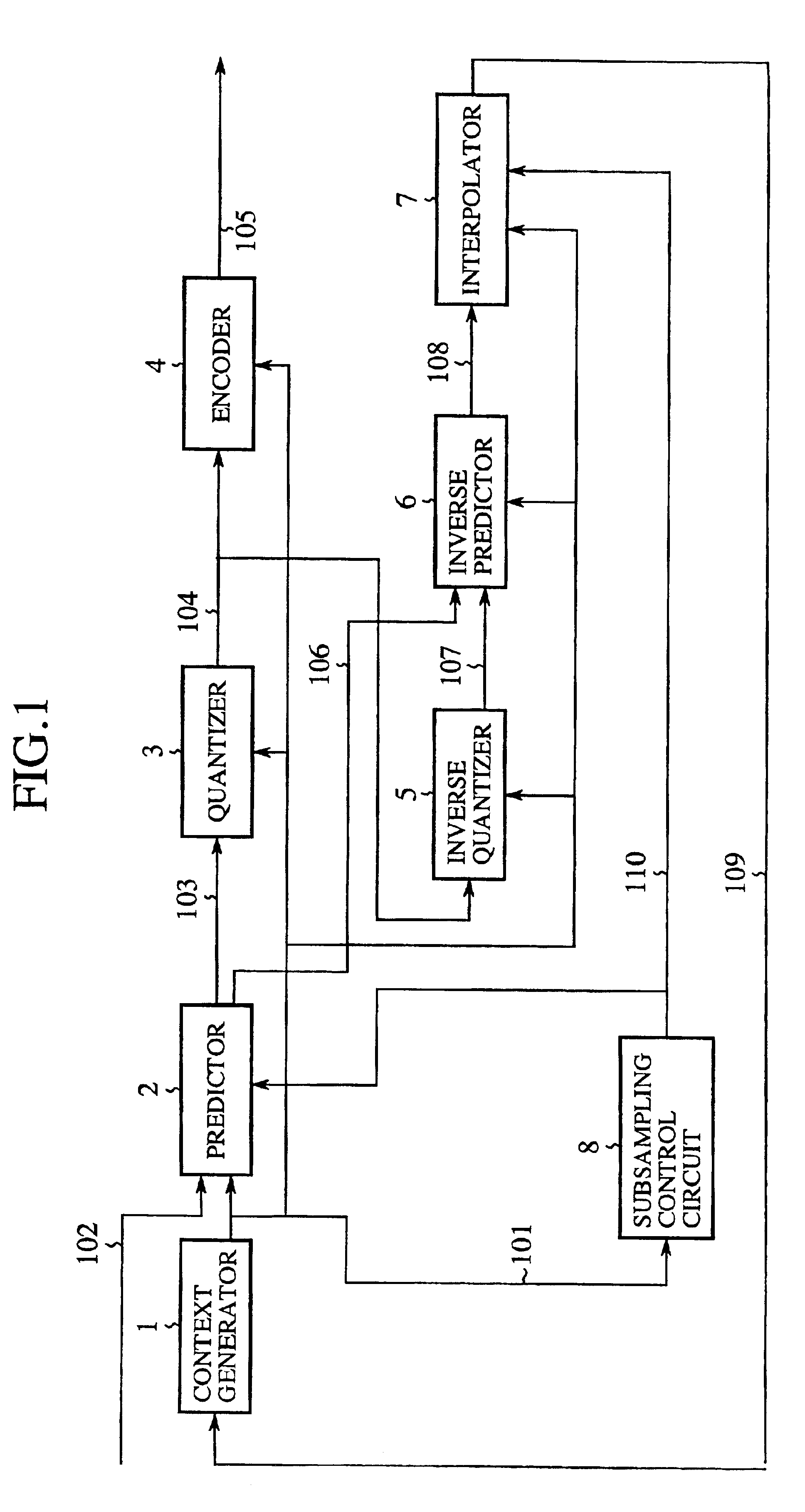
[0033]FIG. 1 shows a construction of an image signal coding apparatus according to a first embodiment of the present invention. Referring to FIG. 1, a context generator 1 generates a context signal 101 identifying a statistical difference of a target pixel 102 (symbol) to be coded from a preceding coded pixel (more strictly, a pixel value indicated by a reconstructed symbol 109 output from an interpolator 7 described later). A predictor 2 performs subsampling in accordance with a subsampling control signal 110 from a subsampling control circuit 8 described later and predicts a coded pixel based on the context signal 101 so as to generate a prediction signal 106 and a prediction error signal 103. A quantizer 3 quantizes the prediction error signal 103 so as to generate a quantized prediction error signal 104. An encoder 4 subjects the quantization prediction error signal 104 to entropy coding. An inverse quantizer 5 subjects the quantized prediction error signal 104 to inverse quanti...

second embodiment

[0074]In the first embodiment, a single predetermined subsampling method is used. In the second embodiment, the subsampling method is controlled while an image is being processed for the purpose of producing a uniform code size.

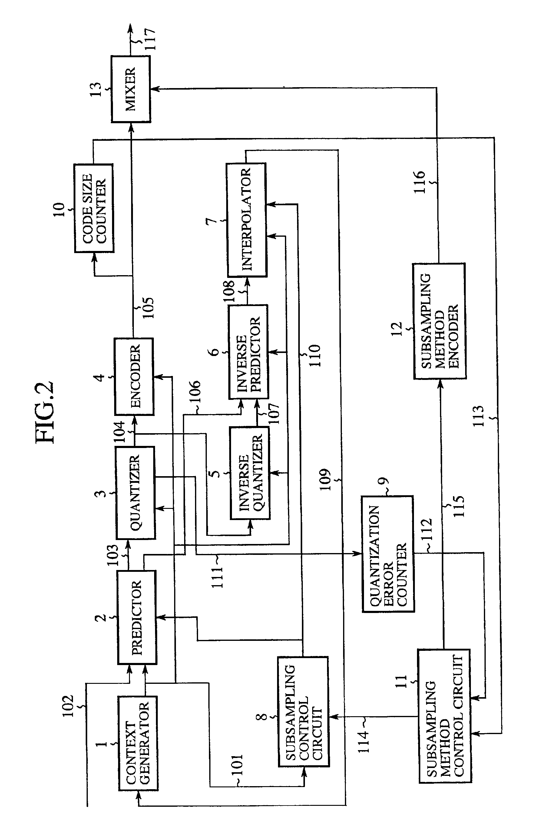
[0075]FIG. 2 shows a construction of an image signal coding apparatus according to a second embodiment of the present invention. Referring to FIG. 2, a quantization error counter 9 counts, for a stripe comprising a plurality of lines, the value indicated by a quantization error signal 111 generated by the quantizer 3 as a result of quantizing the prediction error signal 103, so as to generate a quantization error count 112. A code size counter 10 counts the value indicated by the prediction error coded data 105 in a stripe, so as to generate a code size count 113.

[0076]A subsampling method control circuit 11 uses the quantization error count 112 and the code size count 113 to generate a subsampling method parameter 114 and a subsampling method identification ...

third embodiment

[0093]In the first and second embodiments described above, the subsampling method is controlled based on the coded pixel information. In the third embodiment, a tighter control is effected using the code size and the S / N ratio. According to the third embodiment, a screen of data is stored in a memory prior to coding.

[0094]FIG. 3 shows a construction of an image signal coding apparatus according to the third embodiment of the present invention. Referring to FIG. 3, a memory 14 stores data indicating pixel values of pixels constituting a screen prior to coding. A subsampling control signal encoder 15 codes a subsampling control signal coded data 119. Those components designated by the same reference numerals as the components of the first and second embodiments shown in FIGS. 1 and 2 are the same as the corresponding components.

[0095]A description will now be given of the operation according to the third embodiment. The memory 14 stores data indicating pixel values of pixels for a scr...


PUM


Abstract

A coding apparatus includes: a context generator generating a context signal from a reconstructed symbol; a predictor generating a prediction signal indicating a prediction value which is a prediction of a symbol to be coded, based on the context signal, and a prediction error signal which is a difference between the prediction value and the symbol; a quantizer generating a quantized prediction error signal by quantizing the prediction error signal; an encoder coding the quantized prediction error signal by referring to the context signal; an inverse quantizer subjecting the quantized prediction error signal to inverse quantization so as to generate a reconstructed prediction error signal; an inverse predictor subjecting the reconstructed prediction error signal to inverse prediction so as to generate a reconstructed sampled signal; a subsampling control circuit generating a subsampling control signal indicating whether or not the symbol should be subject to subsampling; and an interpolator referring to the subsampling control signal so as to subject to interpolation the reconstructed sampled signal corresponding to the symbol subject to subsampling, wherein the coding apparatus codes symbols while adaptively employing subsampling.

Description

BACKGROUND OF THE INVENTION[0001]1. Field of the Invention[0002]The present invention generally relates to coding methods, decoding methods, coding apparatuses and decoding apparatuses and, more particularly, to a coding method, a decoding method, a coding apparatus and a decoding apparatus for information source coding and decoding using subsampling.[0003]2. Description of the Related Art[0004]Of two-dimensional signals for which the present invention is adapted, a still image signal composed of Y, Cr and Cb components is taken as an example for description of coding / decoding according to the invention. In coding a still image, signals are often processed by subsampling for reduction of data volume, resulting in the sampling frequency being lowered. For example, the number of sampling points for the Cr and Cb signals may be ½ that of the sampling points of the Y signal. Such a method should however be used only for images containing natural scenery or objects since it produces pseu...

Claims


Application Information

Patent Timeline
IPC IPC(8): H04N7/34H04N7/26H04N7/46H04N1/41H04N19/50H03M7/36H04N19/124H04N19/132H04N19/134H04N19/136H04N19/137H04N19/147H04N19/182H04N19/186H04N19/196H04N19/27H04N19/59H04N19/593H04N19/91
CPCH04N1/41H04N19/147H04N19/46H04N19/13H04N19/149H04N19/59H04N19/593H04N19/124H04N19/132H04N19/136H04N19/186H04N19/169
Inventor SEMASA, TAKAYOSHI
Owner MITSUBISHI ELECTRIC CORP
Why Eureka
Try Eureka