Optical system for calibration and control of an optical fiber switch

a technology of optical fiber switch and optical system, applied in the field of optical system calibration and control of optical fiber switch, can solve the problems of significant bottlenecks in the optical switch that routes optical signals, unmanageable complex devices for large n, time delay and cost, etc., and achieve the effect of reducing the loss of optical switch insertion and high resolution control

Inactive Publication Date: 2005-05-24
INTEL CORP
View PDF15 Cites 24 Cited by
  • Summary
  • Abstract
  • Description
  • Claims
  • Application Information

AI Technical Summary

Benefits of technology

[0010]The present invention provides methods of calibrating and operating optical switches. A method of calibrating an optical switch including a first port, a second port, a first mirror and a second mirror in accordance with the present invention includes directing a first control beam of light onto the first mirror and directing a second control beam of light onto the second mirror. The method also includes controlling an orientation of the first mirror such that the first mirror reflects the first control beam of light to a predetermined position on a first position sensing detector, and controlling an orientation of the second mirror such that the second mirror reflects the second control beam of light to a predetermined position on a second position sensing detector. A third beam of light (e.g., at a telecommunications wavelength) incident on the first mirror from the first port is thereby directed to the second mirror and thence to the second port. The method further includes controlling the orientations of the first mirror and the second mirror to maximize the intensity of the third beam of light coupled into the second port, and recording signals determined from outputs provided by the first and second position sensing detectors.
[0012]This calibration method, which is typically performed only once in the factory after assembly of the optical switch, allows highly accurate control of the mirrors in the optical switch during subsequent switching operations in the field.
[0015]The first, second, and third control light beams utilized in the operation method are separate from the light beams being routed through and switched by the optical switch. Hence, the mirrors in the optical switch can be aligned to couple signal (e.g., telecommunications) light beams input through particular input ports to particular output ports before those signal light beams are provided to the optical switch. Moreover, the orientations of the mirrors may be controlled without sampling the signal light beams, thus reducing the insertion loss of the optical switch.
[0016]The present invention also provides optical switches in which the orientations of mirrors are measured and controlled using control light beams and position sensing detectors. In one embodiment, an optical switch includes a plurality of mirrors, a light source located to illuminate the plurality of mirrors, a plurality of position sensing detectors, and an imaging system located to image the plurality of mirrors at an image plane spaced apart from the detectors. Signals provided by the position sensing detectors correspond to orientations of corresponding mirrors. This arrangement allows the orientations of the plurality of mirrors to be measured and controlled with, for example, a resolution of better than about 0.04° over a range of greater than about 20° (about 9 bit accuracy).
[0019]The high resolution control of mirror orientations achievable in optical switches provided by embodiments of the present invention reduces the insertion loss of the optical switches. Consequently, optical fiber switches may be controlled in accordance with embodiments of the present invention to cross-connect more than a thousand input ports to more than a thousand output ports with an insertion loss of less than, for example, about 3 decibels.

Problems solved by technology

As optical fiber progressively supplements and replaces metal wire as the backbone of telecommunications networks, the switches that route optical signals have emerged as a significant bottleneck.
Electronic switching requires light to be converted to an electronic signal to pass through the switch and then be reconverted to light in a process termed optical-electronic-optical (OEO) conversion that introduces both time delay and cost.
Unfortunately, N2 scaling results in unmanageably complex devices for large N.

Method used


Image

  • Optical system for calibration and control of an optical fiber switch
  • Optical system for calibration and control of an optical fiber switch
  • Optical system for calibration and control of an optical fiber switch

Examples


Embodiment Construction

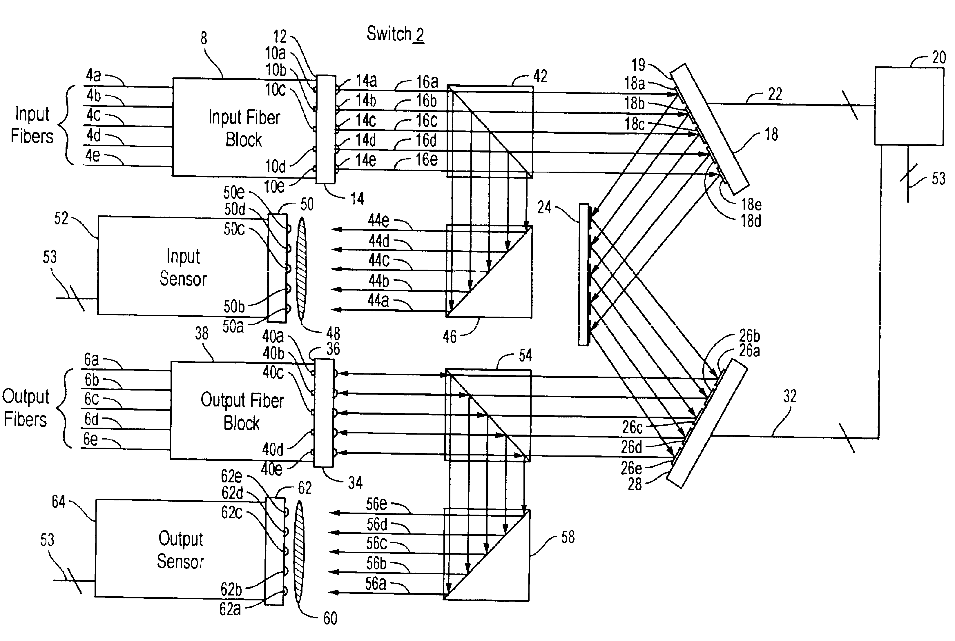
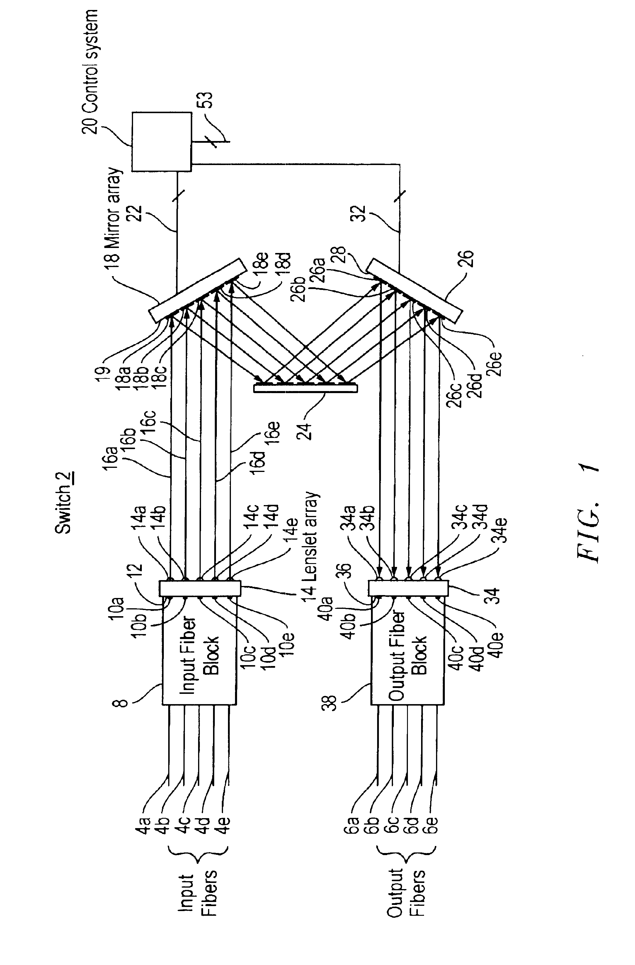
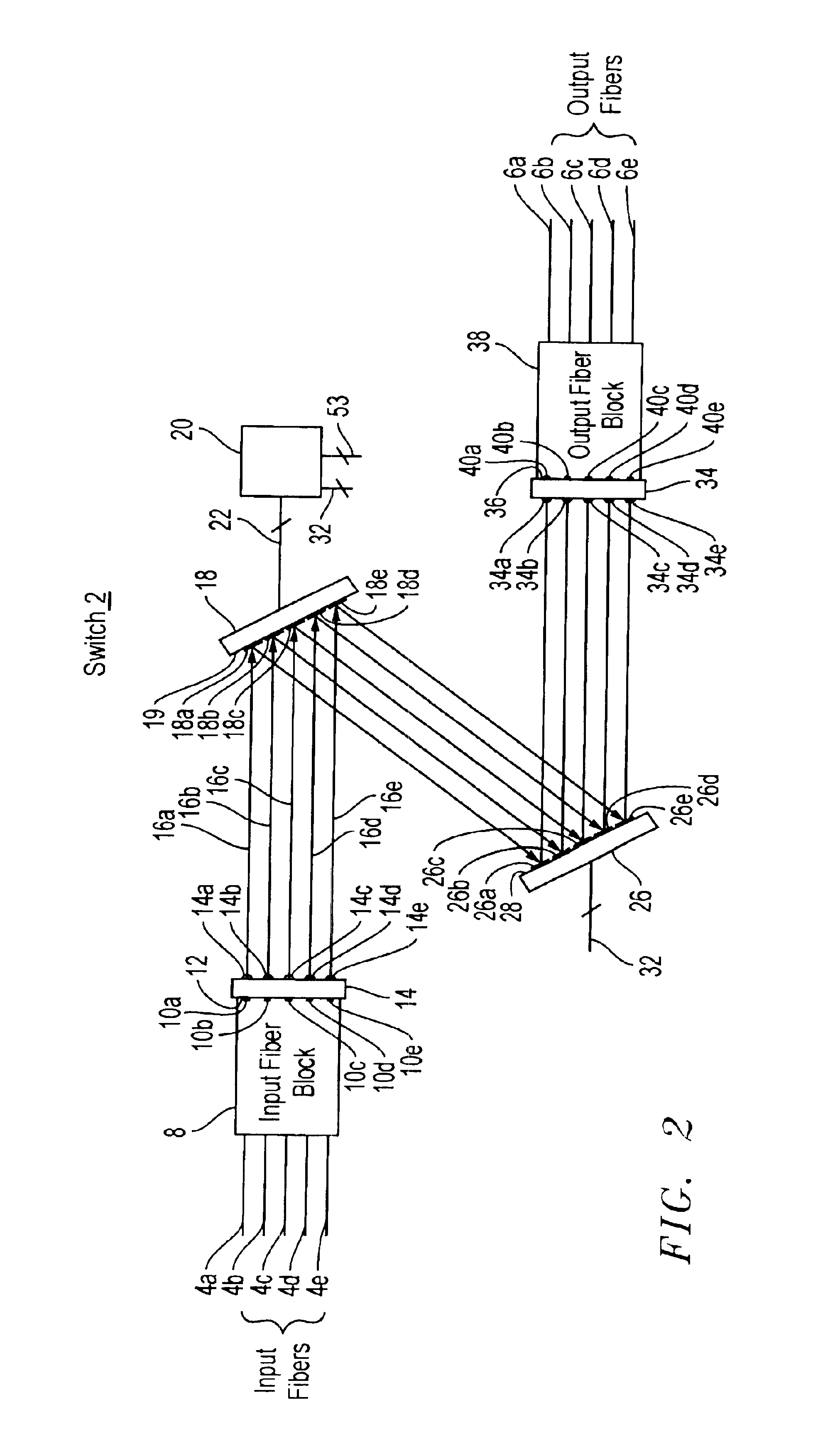
[0036]An optical fiber cross-connect switch in accordance with embodiments of the present invention routes light input through any one of N input ports to any one of P output ports. In a typical optical path through a switch, light entering the switch through an input port is incident on a corresponding first micro-mechanical mirror in a first two dimensional array of micro-mechanical mirrors. The first micro-mechanical mirror, which can be oriented in a range of arbitrary directions (dθ,dφ), is tilted to direct the light to a second micro-mechanical mirror in a second two dimensional array of micro-mechanical mirrors. The second micro-mechanical mirror, which can also be oriented in a range of arbitrary directions (dθ,dφ), is tilted to direct the light to a corresponding output port and hence out of the switch.

[0037]The light may be switched from the output port to which it is initially directed to another output port by reorienting the first micro-mechanical mirror to direct the l...


PUM


Abstract

Methods of calibrating and operating optical switches as well as optical switches in which the orientations of mirrors are measured and controlled using control light beams and position sensing detectors are described. The present invention may provide high resolution control of a plurality of mirrors in an optical switch and thus allow the optical switch to cross-connect a large number of input and output ports with a low insertion loss.

Description

CROSS REFERENCE TO RELATED APPLICATIONS[0001]This application is related to the following co-filed, commonly assigned, U.S. Patent Applications: U.S. patent application Ser. No. 09 / 999,878, U.S. patent application Ser. No. 09 / 999,705, U.S. patent application Ser. No. 09 / 779,189 now U.S. Pat. No. 6,480,320, U.S. patent application Ser. No. 10 / 003,659 now U.S. Pat. No. 6,614,954, and U.S. patent application Ser. No. 10 / 002,310 now U.S. Pat. No. 6,636,656, all of which arc incorporated herein by reference. This application is also related to U.S. patent application Ser. No. 09 / 779,189, entitled “A Microelectrornechanical Mirror,” filed Feb. 7, 2001, assigned to the assignee of the present invention, and incorporated herein by reference.BACKGROUND OF THE INVENTION[0002]1. Field of the Invention[0003]The present invention relates to optical fiber cross-connect switching.[0004]2. Description of the Related Art[0005]As optical fiber progressively supplements and replaces metal wire as the ...

Claims


Application Information

Patent Timeline
Patent Type & Authority Patents(United States)
IPC IPC(8): G02B6/35H04Q11/00G02B6/42G02B26/08H04Q3/52
CPCG02B6/3586H04Q11/0005G02B6/3546G02B6/3556H04Q2011/0083H04Q2011/003H04Q2011/0037H04Q2011/0039H04Q2011/0049H04Q2011/0026
Inventor HUANG, CHENG-CHUNGNASIRI, STEVEN SAEEDSPRAGUE, RANDALL BRIANHARWIT, ALEXBAKIN, DMITRY VASILYBRYZEK, JANUSZ
Owner INTEL CORP
Why Eureka
Try Eureka