Fixing apparatus

a technology of fixing apparatus and fixing rod, which is applied in the direction of electrographic process apparatus, shaft and bearing, instruments, etc., can solve the problems of not considering the following problems, and achieve the effect of effective utilization

Inactive Publication Date: 2005-05-24
KK TOSHIBA +1
View PDF17 Cites 43 Cited by
  • Summary
  • Abstract
  • Description
  • Claims
  • Application Information

AI Technical Summary

Benefits of technology

[0012]The present invention has been achieved with the above situations in view and the object of the present invention provides a fixing apparatus which has measures against problems likely to be produced in a practical application and can effectively utilize them in the case where either one or both of a heating rotation body and pressing rotation body have a conductive layer formed on an elastic layer.

Problems solved by technology

In the prior art, however, no consideration has been paid to the following problems likely to occur in a practical application.

Method used


Image

  • Fixing apparatus
  • Fixing apparatus
  • Fixing apparatus

Examples


first embodiment

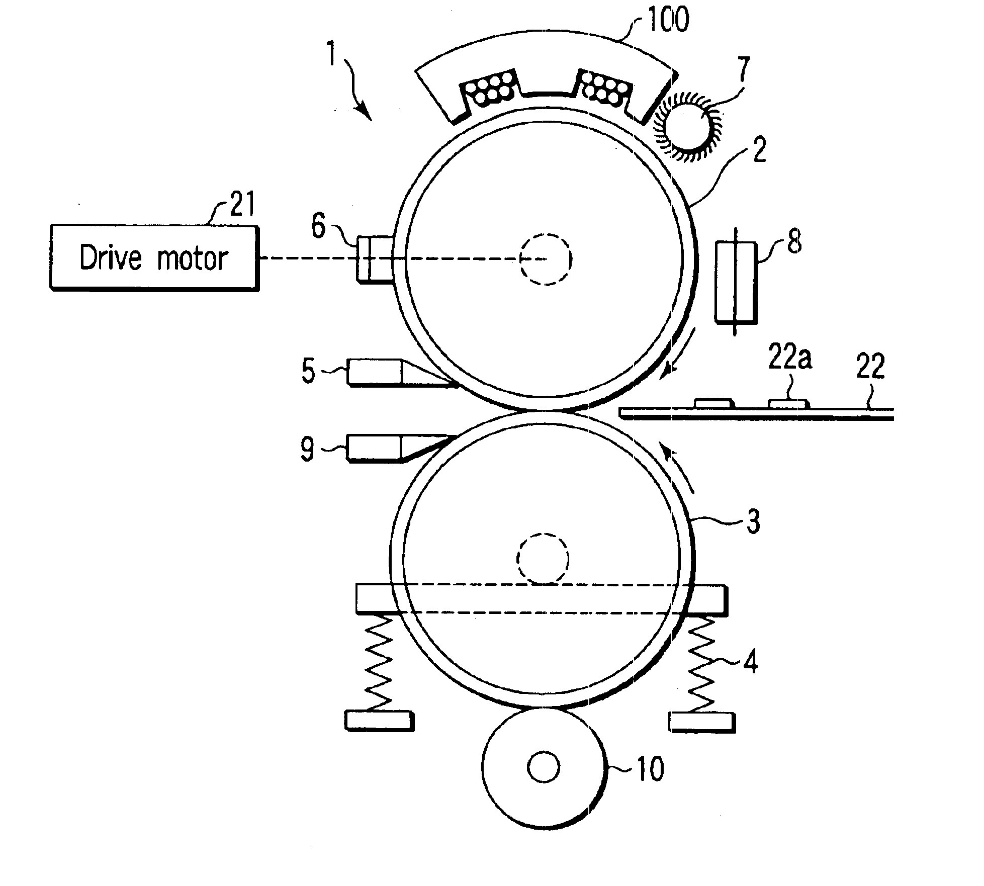
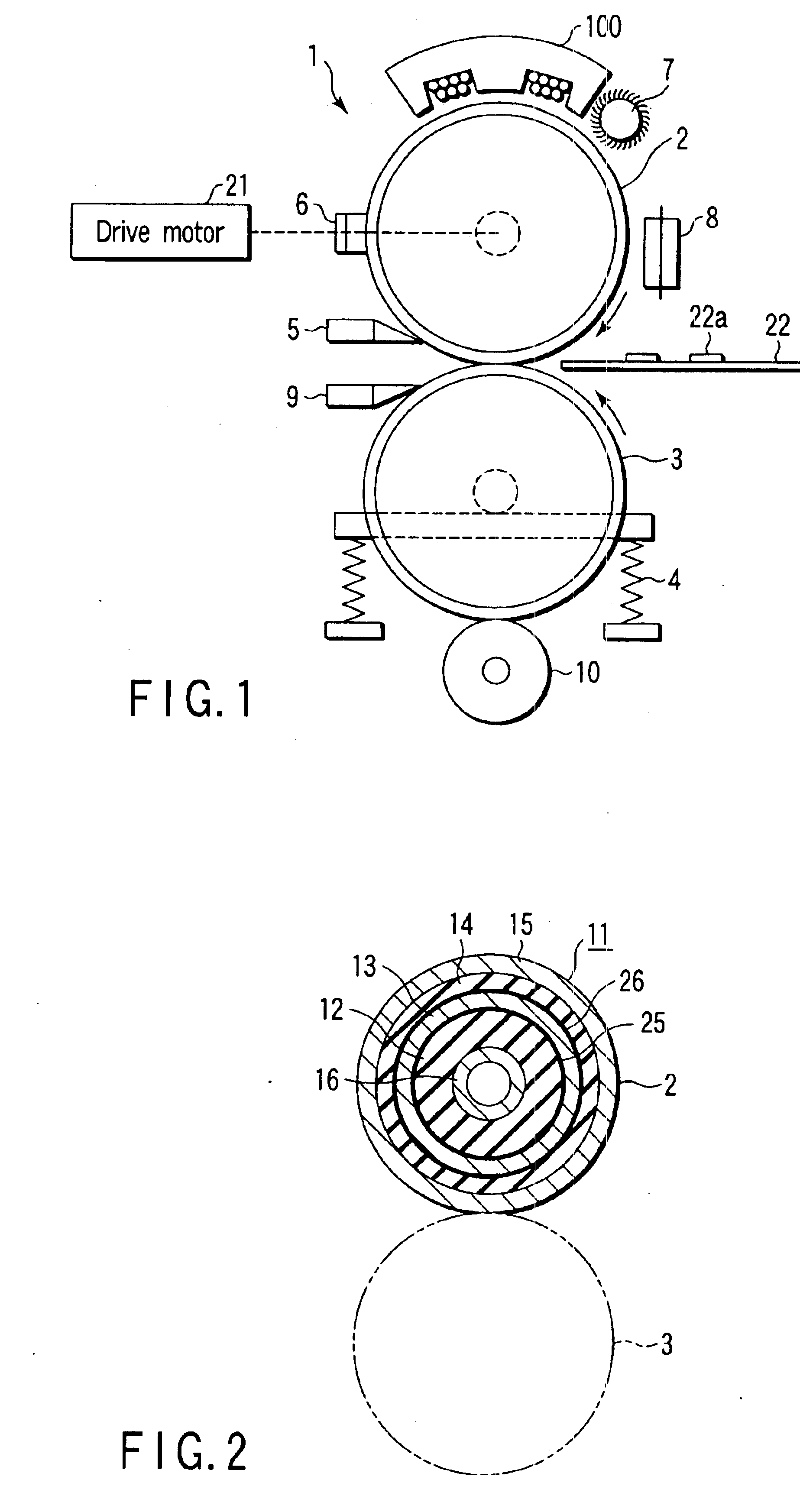
[0033]FIG. 1 is a schematic view diagrammatically showing a whole of a fixing apparatus 1 according to the present invention.

[0034]The fixing apparatus 1 is provided in an image forming apparatus and is configured to have a heating (heat) roller 2 (diameter 40 mm) formed as a heating rotation body and a pressing (press) roller 3 (diameter 40 mm) formed as a pressure applying rotation body. As the heating roller 2 use is made of an endless member 11 as shown in FIG. 2. A detailed structure of the endless member 11 will be described below.

[0035]The pressing roller 3 is formed with a rubber such as silicone, fluorine, etc., covered on a peripheral surface of its core member. The pressing roller 3 is pressed by a pressure application mechanism 4 against the heating roller 2 and maintained to have a predetermined nip width.

[0036]The heating roller 2 is driven by a drive motor 21 in the direction of an arrow and the pressing roller 3 is rotated as a driven roller in a direction of an arro...

second embodiment

[0068]The peripheral speed D of the heating roller 2 is detected by the same method as that of the Details of it are omitted. In the image forming apparatus used in this invention, a slip detection routine is provided for detecting a slip between the rotationally driven heating roller 2 and the pressing roller 2.

[0069]FIG. 9 is a flowchart showing the slip detection routine.

[0070]In this self-diagnostic routine, first, the peripheral speed C of the pressing roller 3 is found from the relation between the rotation speed (angular velocity) by a drive force loaded on the pressing roller 3 and the radius of the roller 3 (step ST11). Then, the peripheral speed D of the heating roller 2 is detected by a detecting means (step ST12).

[0071]In order to decide a large / small relation between these values C and D the difference C−D is found (step ST13).

[0072]The peripheral speeds C and D become equal when there is no slip between the rollers 2 and 3 and becomes C>D when there occurs a slip betw...

fifth embodiment

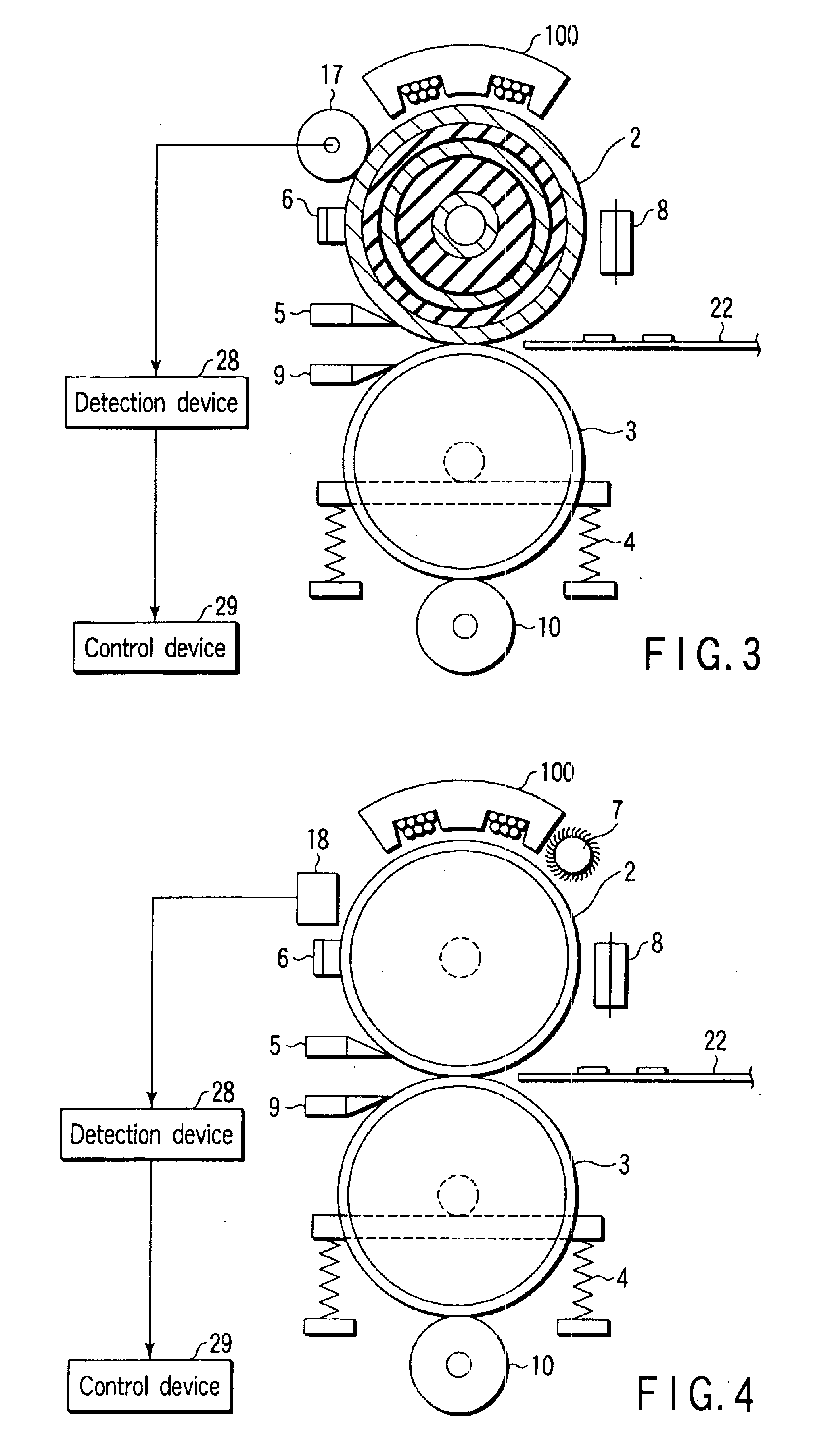
[0083]FIG. 11 is a schematic view showing a fixing apparatus according to the present invention.

[0084]It seems that the endless member 11 is softer and readily deformable and that, during a prolonged period, it is more liable to be deformed and to be so due to a thermal expansion at the time of heating than expected.

[0085]Thus it is also considered that, in the structure of the first embodiment, the separation claw 5 on the heating roller 2 side is moved away from the surface of the roller 2 due to the deformation of the roller 2 and it is more forcibly urged against the roller then expected and does not function as expected.

[0086]In the fifth embodiment, therefore, a separation blade 20 is retained by an adjusting blade 20 and positioning rollers 19, 19 are mounted on both ends to allow these rollers to abut against the surface of the heating roller 2 by means of an urging mechanism not shown. By doing so, as shown in FIG. 12, a given distance is always retained between the heating...


PUM


Abstract

A fixing apparatus includes a fixing device configured to, by allowing a sheet having a developing agent image on it to pass between a heating roller and a pressing roller set in contact with the heating roller, fix the developing agent image in which at least one of the heating roller and pressing roller is configured to have an inner elastic layer and a conductive layer formed on a surface side of the elastic layer and the elastic layer is bonded to the conductive layer by a heat-resistant adhesive having a heat-resistant temperature of over 200° C.

Description

BACKGROUND OF THE INVENTION[0001]The present invention relates to a fixing apparatus for use, for example, in an image forming apparatus.[0002]This type of fixing apparatus is disclosed, for example, in Jpn. Pat. Appln. KOKAI Publication Nos. 2002-49261, 2001-188427 and 10-63126.[0003]A fixing roller of the fixing apparatus disclosed in Jpn. Pat. Appln. KOKAI Publication No. 2002-49261 has a cylindrical rigid body in which a layer of a lower heat conduction material, a conductive layer of an electroconductive material and a mold releasing layer are sequentially formed on an outer side of the rigid body. Near the fixing roller, an induction heating source is provided opposite to the outer peripheral surface of the roller.[0004]By inductively heating the conductive layer of the fixing roller by means of the induction heating source it is possible to heat the fixing roller in a short time to a desired temperature.[0005]A fixing apparatus disclosed in Jpn. Pat. Appln. KOKAI Publication ...

Claims


Application Information

Patent Timeline
Patent Type & Authority Patents(United States)
IPC IPC(8): F16C13/00G03G15/20
CPCG03G15/2064G03G15/206G03G2215/2051
Inventor TSUEDA, YOSHINORIKINOUCHI, SATOSHITAKAGI, OSAMUSONE, TOSHIHIRO
Owner KK TOSHIBA
Why Eureka
Try Eureka