Locking system for mechanical joining of floorboards and method for production thereof

a locking system and floorboard technology, applied in the direction of walls, building components, constructions, etc., can solve the problems of insufficient manufacturing tolerance, inability to provide space for manufacturing tolerances, and inability to provide satisfactory solutions, etc., to achieve the effect of thin floor structur

Inactive Publication Date: 2005-05-31
VÄLINGE INNOVATION AB
View PDF321 Cites 128 Cited by
  • Summary
  • Abstract
  • Description
  • Claims
  • Application Information

AI Technical Summary

Benefits of technology

[0023]Although the floor according to WO 94 / 26999 and WO 99 / 66151 and the floor sold under the trademark Fiboloc® exhibit major advantages in comparison with traditional, glued floors, further improvements are desirable mainly in thin floor structures.
[0030](iii) a strip and a locking element, which have high strength and good function.

Problems solved by technology

In thin floorboards, it is difficult to provide, with prior-art technique, a joint system which at the same time has a sufficiently high and stable upper part, a thick, strong and rigid tongue and a sufficiently thick strip with a high locking element.
Nor does a joint system according to FIG. 4d, i.e. according to U.S. Pat. No. 4,426,820, solve the problem since a tongue groove with upper and lower contact surfaces which are parallel with the upper side of the floorboard or the floor plane, cannot be manufactured using the milling tools which are normally used when making floorboards.
The rest of the joint geometry in the design according to FIG. 4d cannot be manufactured by working a wood-based board since all surfaces abut each other closely, which does not provide space for manufacturing tolerances.
At present there are no known products or methods which afford satisfactory solutions to problems that are related to thin floorboards with mechanical joint systems.
It has been necessary to choose compromises which (i) either result in a thin tongue and sufficient material thickness in the joint edge portion above the corresponding tongue groove in spite of plane-parallel contact surfaces or (ii) use upper and lower contact surfaces angled to each other and downwardly extending projections and corresponding recesses in the tongue and the tongue groove respectively of adjoining floorboards or (iii) result in a thin and mechanically weak locking strip with a locking element of a small height.

Method used


Image

  • Locking system for mechanical joining of floorboards and method for production thereof
  • Locking system for mechanical joining of floorboards and method for production thereof
  • Locking system for mechanical joining of floorboards and method for production thereof

Examples


Embodiment Construction

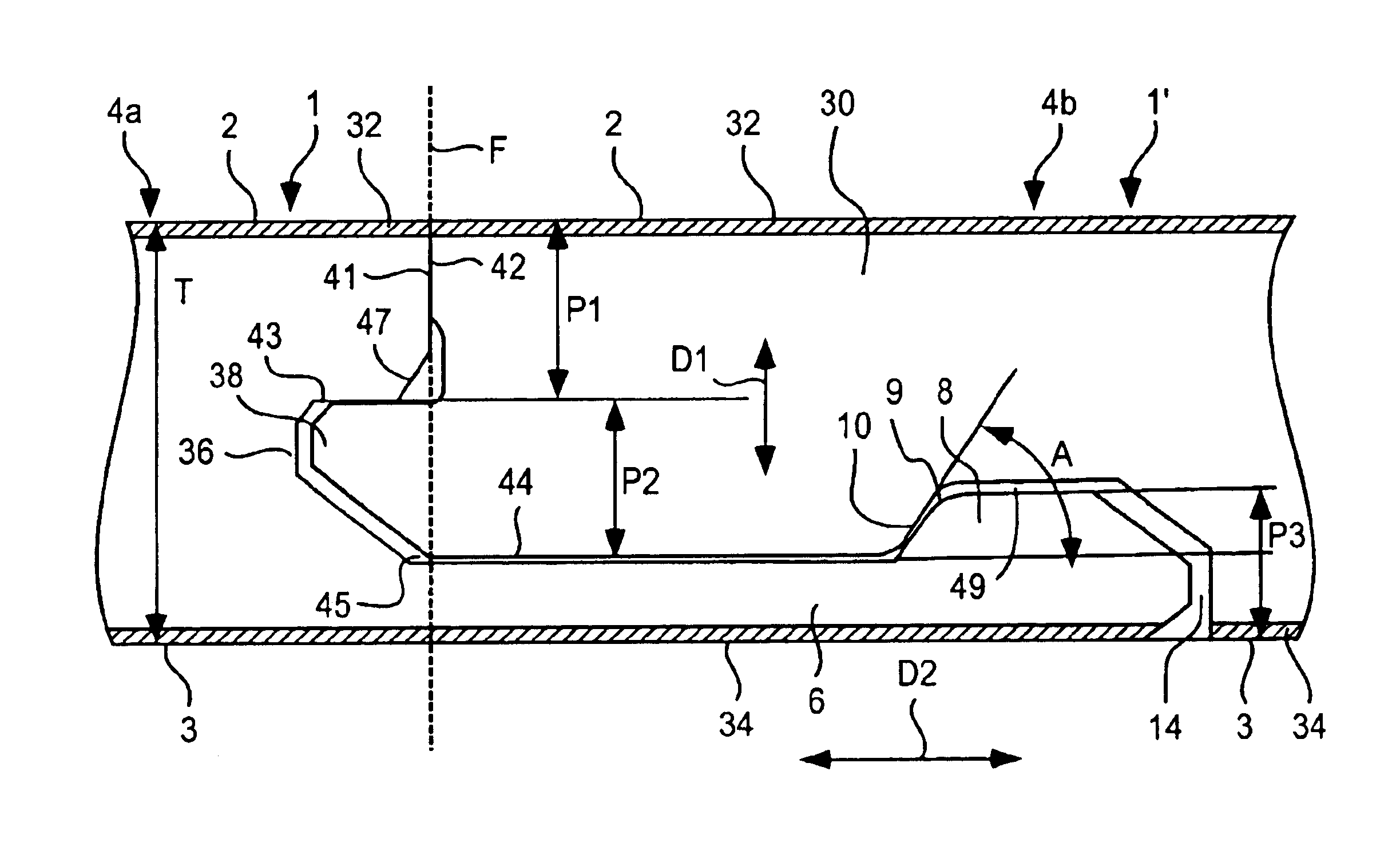
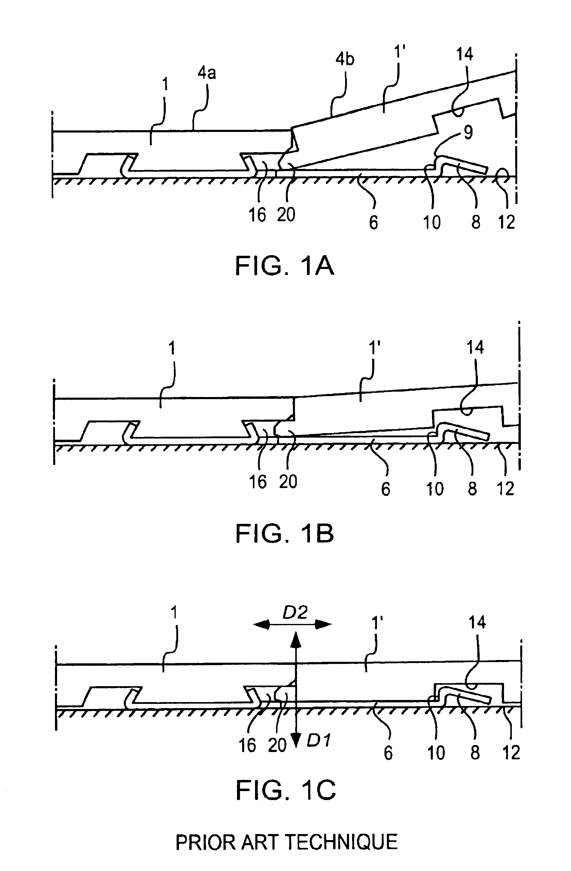
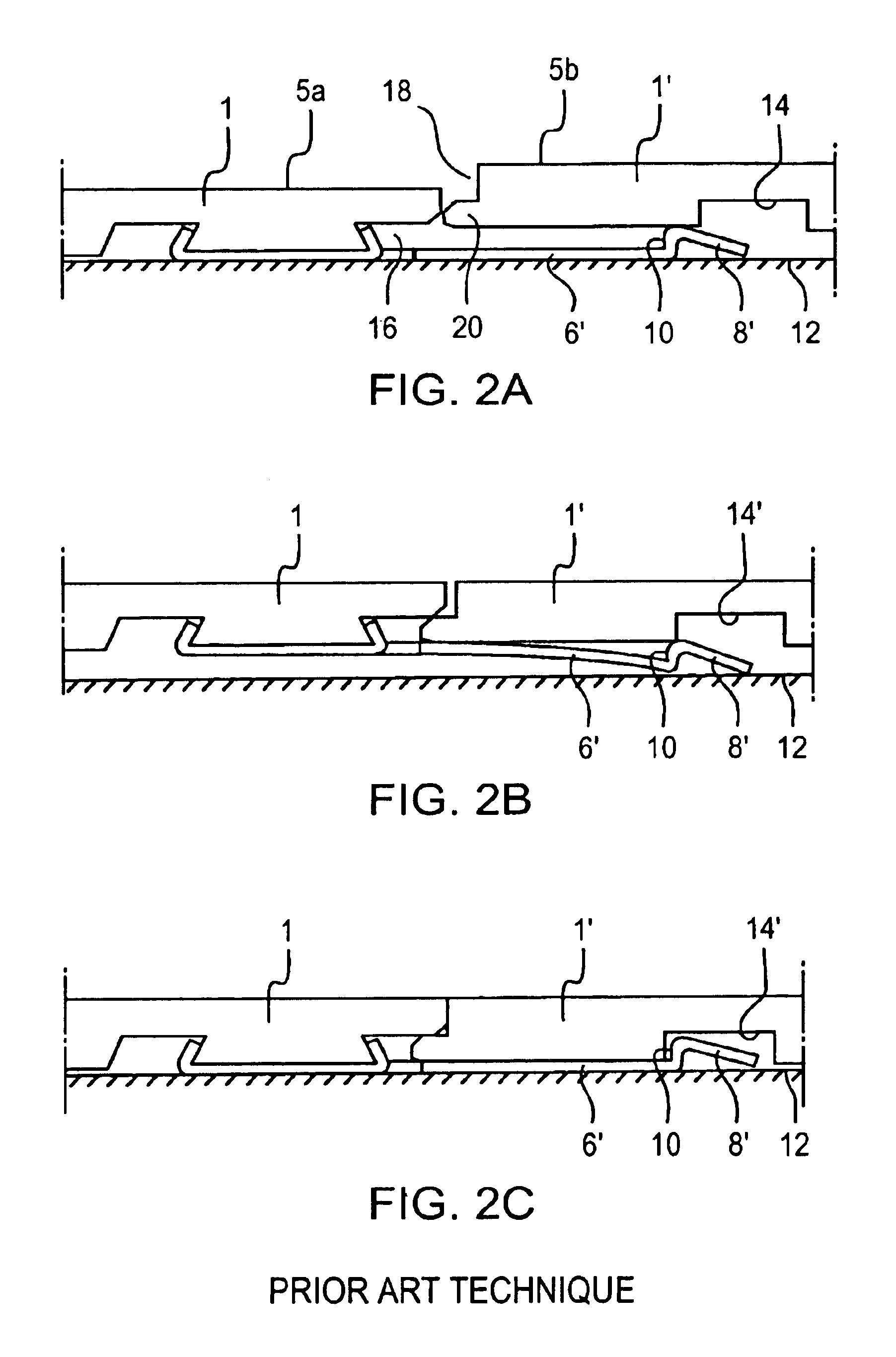
[0055]Prior to the description of preferred embodiments, with reference to FIG. 5, a detailed explanation will first be given of the most important parts in a strip lock system.

[0056]The cross-sections shown in FIG. 5 are hypothetical, not published cross-sections, but they are fairly similar to the locking system of the known floorboard “Fiboloc®” and to the locking system according to WO 99 / 66151. Accordingly, FIG. 5 does not represent the invention. Parts corresponding to those in the previous Figures are in most cases provided with the same reference numerals. The construction, function and material composition of the basic components of the boards in FIG. 5 are essentially the same as in embodiments of the present invention, and consequently, where applicable, the following description of FIG. 5 also applies to the subsequently described embodiments of the invention.

[0057]In the embodiment shown, the boards 1, 1′ in FIG. 5 are rectangular with opposite long sides 4a, 4b and opp...


PUM


Abstract

The invention relates to a locking system for mechanical joining of floorboards (1, 1′) which have a body (30), a lower balancing layer (34) and an upper surface layer (32). A strip (6) is integrally formed with the body (30) of the floorboard (1) and extends under an adjoining floorboard (1′). The strip (6) has a locking element (8), which engages a looking groove (14) in the underside of the adjoining floorboard (1′) and forms a horizontal joint. A tongue (38) and a tongue groove (36) form a vertical joint between upper and lower plane-parallel contact surfaces (43, 45) and are designed in such manner that the lower contact surfaces (45) are on a level between the upper side of the locking element (8) and a plane containing the underside (3) of the floorboard. The invention also relates to a floorboard having such a locking system, a floor made of such floorboards, as well as a method for making such a locking system.

Description

[0001]This application is a continuation of U.S. application Ser. No. 09 / 954,066, filed on Sep. 18, 2001, now U.S. Pat. No. 6,510,665 which was a continuation of International Application No. PCT / SE01 / 00125, filed on Jan. 24, 2001, which International Application was published by the International Bureau in English on Jul. 26, 2001. The entire contents of PCT / SE01 / 00125 are hereby incorporated herein by referenceTECHNICAL FIELD[0002]The invention generally relates to the field of mechanical locking of floorboards. The invention relates to an improved locking system for mechanical locking of floorboards, a floorboard provided with such an improved locking system, a flooring made of such mechanically joined floorboards, and a method for making such floorboards. The invention generally relates to an improvement of a locking system of the type described and shown in WO 94 / 26999 and WO 99 / 66151.[0003]More specifically, the invention relates to a locking system for mechanical joining of f...

Claims


Application Information

Patent Timeline
Patent Type & Authority Patents(United States)
IPC IPC(8): E04F15/04B27M3/00B27F1/02B27M3/02B27M3/04E04F13/08E04F15/02
CPCE04F15/02E04F15/04E04F2201/0107Y10T428/167E04F2201/0153E04F2201/042E04F2201/0517E04F2201/0115
Inventor PERVAN, DARKO
Owner VÄLINGE INNOVATION AB
Why Eureka
Try Eureka