Mounting transponders and antennas in pneumatic tires

Inactive Publication Date: 2005-05-31
THE GOODYEAR TIRE & RUBBER CO
View PDF27 Cites 93 Cited by
  • Summary
  • Abstract
  • Description
  • Claims
  • Application Information

AI Technical Summary

Benefits of technology

[0054]It is another aspect to provide method and apparatus for mounting a transponder module in a pneumatic tire in a manner such that the transponder may conveniently be insert

Problems solved by technology

Failure to correct quickly for faulty/abnormal (typically low) air pressure may result in excessive tire wear, blow-outs, poor gasoline mileage and steering difficulties.
Although the use of pressure transducers in pneumatic tires (in association with electronic circuitry for transmitting pressure data, such as transponder) is generally well known, these pressure-data systems for tires have been plagued by difficulties inherent in the tire environment.
Such difficulties include effectively and reliably coupling RF signals into and out of the tire, the rugged use the tire and electronic components are subjected to, as well as the possibility of deleterious effects on the tire from incorporation of the pressure transducer and electronics in a tire/wheel system.
One challenge associated with mounting the transponder (module), is ensuring that the pressure sensor component of the transponder is in fluid communication with the cavity of the tire so that air pressure within the tire can be detected/measured.
sensor. Typically, in the mounting techniques of the prior art, the transponder is not readily accessible for replacement or mai
Another challenge when mounting a transponder or a housing (cover) for the transponder (see, e.g., FIG. 10 and the cover 80 of the aforementioned U.S. Pat. No. 5,500,065% during building the tire, is inherent in putting any “foreign object” on the tire building drum during lay-up of the green tire.
Such a “lump” on an otherwise substantially cylindrical build drum can interfere with (adversely affe

Method used


Image

  • Mounting transponders and antennas in pneumatic tires
  • Mounting transponders and antennas in pneumatic tires
  • Mounting transponders and antennas in pneumatic tires

Examples


Example

An Exemplary Transponder Module

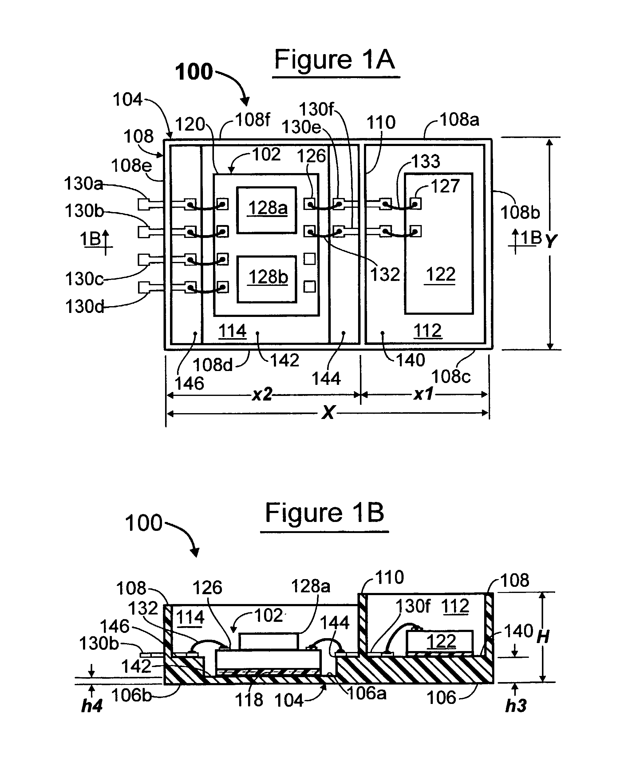
[0130]FIGS. 1A and 1B, comparable to FIGS. 9A and 9B of the commonly-owned, copending PCT Patent Application No. PCT / US98 / 07578, illustrate an exemplary transponder module 100 for monitoring tire pressure. The present invention is not limited to this particular exemplary transponder module.

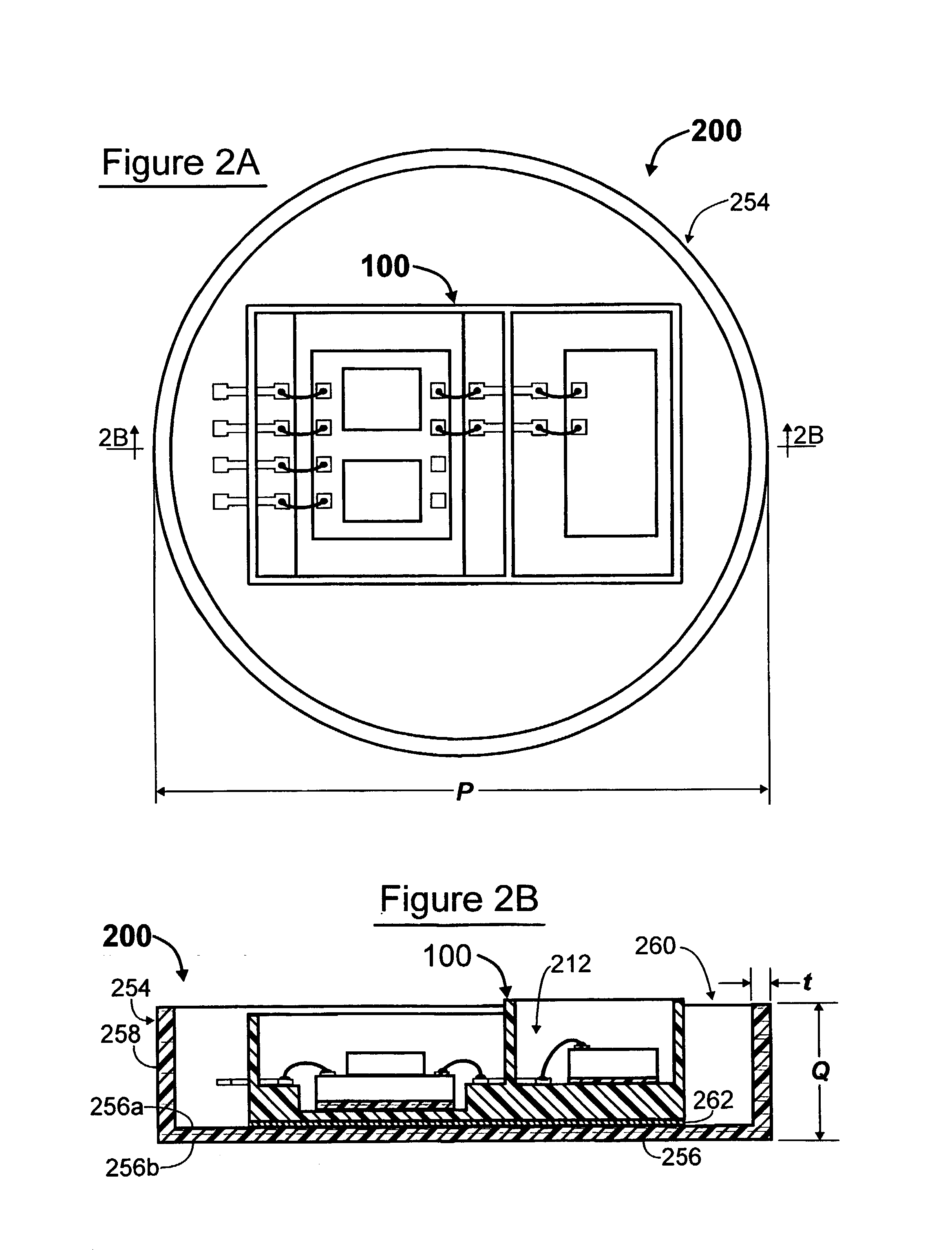
[0131]In this exemplary transponder module 100, circuitry is encapsulated in an encapsulation package (housing) 104 that has two side-by-side chambers 112 and 114 which can be filled with potting compound. In this and subsequent examples of transponder modules (e.g., 200), the potting compound is omitted from the illustrations for illustrative clarity, it being understood that the present invention is suitable for retaining a variety of transponder modules, whether potted or not, on an inside surface of a tire, as described in greater detail hereinbelow.

[0132]The encapsulation package 104 has a generally planar base portion 106. The base portion 106 has an inner surf...


PUM

PropertyMeasurementUnit
Electrical conductoraaaaaaaaaa

Abstract

An antenna comprises two elongate antenna segments (740, 740′, 862, 940, 970, 1208/1212, 1300, 1320, 1322/1324, 1360, 1360′, 1520, 1520′, 1520″, 1523, 1523′, 1620, 1720, 1820, 1920) which extend from first ends (742, 742′, 864, 942, 972, 1322e, 1362, 1362′, 1522, 1522′, 1522″, 1622, 1922)/(744, 744′, 868, 944, 974, 1324e, 1364, 1364′, 1524, 1524′, 1524″, 1624, 1924) connected to the antenna coupling coil in opposite directions to second ends (744, 744′, 868, 944, 974, 1322c, 1366, 1366′, 1524, 1524′, 1524″, 1624, 1924)/(742, 742′, 864, 942, 972, 1324c, 1368, 1368′, 1522, 1522′, 1522″, 1622, 1922) at least partially around the inner surface of the tire. The antenna and antenna coupling coil are mounted to the inner surface of the tire, and the transponder module is attached to the antenna coupling coil in a way which positions the transponder coupling coil in close proximity and concentric to the antenna coupling coil, thereby providing effective transformer-type coupling between the transponder and the antenna.

Description

TECHNICAL FIELD OF THE INVENTION[0001]The invention relates to the mounting of electronic devices such as transponders and antennas in pneumatic tires, and to the coupling of transponders to antennas in pneumatic tires.BACKGROUND OF THE INVENTIONTHE ASSIGNEE'S ONGOING DEVELOPMENT EFFORTS[0002]For a century, the Goodyear Tire & Rubber Company of Akron Ohio, assignee of the present invention, has been the uncontested industry leader in tire product technology. For example, as early as 1892, a puncture-resistant tire was patented. In 1934, a year recognized as the beginning of the run-flat era, Goodyear introduced the Lifeguard (tm) safety tube, a fabric tube within the tire, used commercially by auto makers and on trucks.[0003]In 1993, Goodyear's Eagle GS-C EMT (Extended Mobility Tire) won the Discover Award for Automotive Technological Innovation. In 1996, the Goodyear Eagle F1 run-flat tire was chosen as standard equipment on the 1997 Chevrolet C-5 Corvette.[0004]Other examples of t...

Claims


Application Information

Patent Timeline
IPC IPC(8): B60C23/04B60C23/02
CPCB60C23/0408
Inventor POLLACK, RICHARD STEPHENBROWN, ROBERT WALTERLETKOMILLER, JOSEPH MICHAELHUNT, LOREN FIELDING
Owner THE GOODYEAR TIRE & RUBBER CO
Why Eureka
Try Eureka