
Bottle crate

a technology for bottles and crates, applied in the field of bottles crates, can solve the problems of crates under these conditions affecting the quality of bottles, and achieve the effect of efficient operation

Inactive Publication Date: 2005-05-31
REHRIG PACIFIC CO INC
View PDF41 Cites 33 Cited by
  • Summary
  • Abstract
  • Description
  • Claims
  • Application Information

AI Technical Summary

Benefits of technology

[0006]It is an object according to the present invention to provide an improved crate for bottles which is able to work efficiently with automated handling devices.
[0007]It is another object according to the present invention to provide an improved crate for bottles which is more durable and subject to less deflection and deformation.
[0008]It is another object according to the present invention to provide an improved crate for bottles having corner areas which are adapted to better withstand the stresses placed on such crates.

Problems solved by technology

Crates under these conditions may eventually fail due to the repeated stress, deflection, and deformation.

Method used


Image

  • Bottle crate
  • Bottle crate
  • Bottle crate

Examples


Embodiment Construction

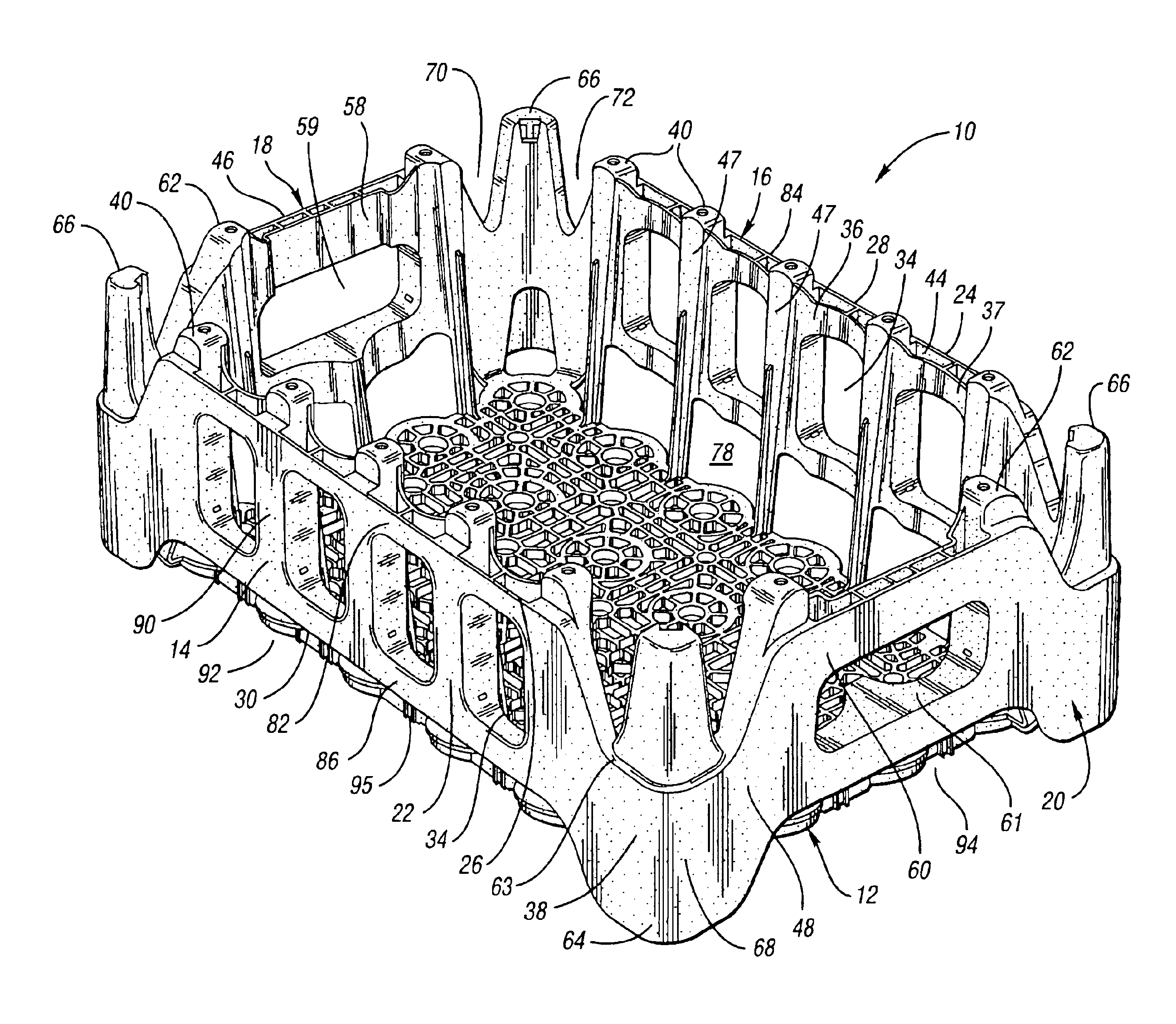
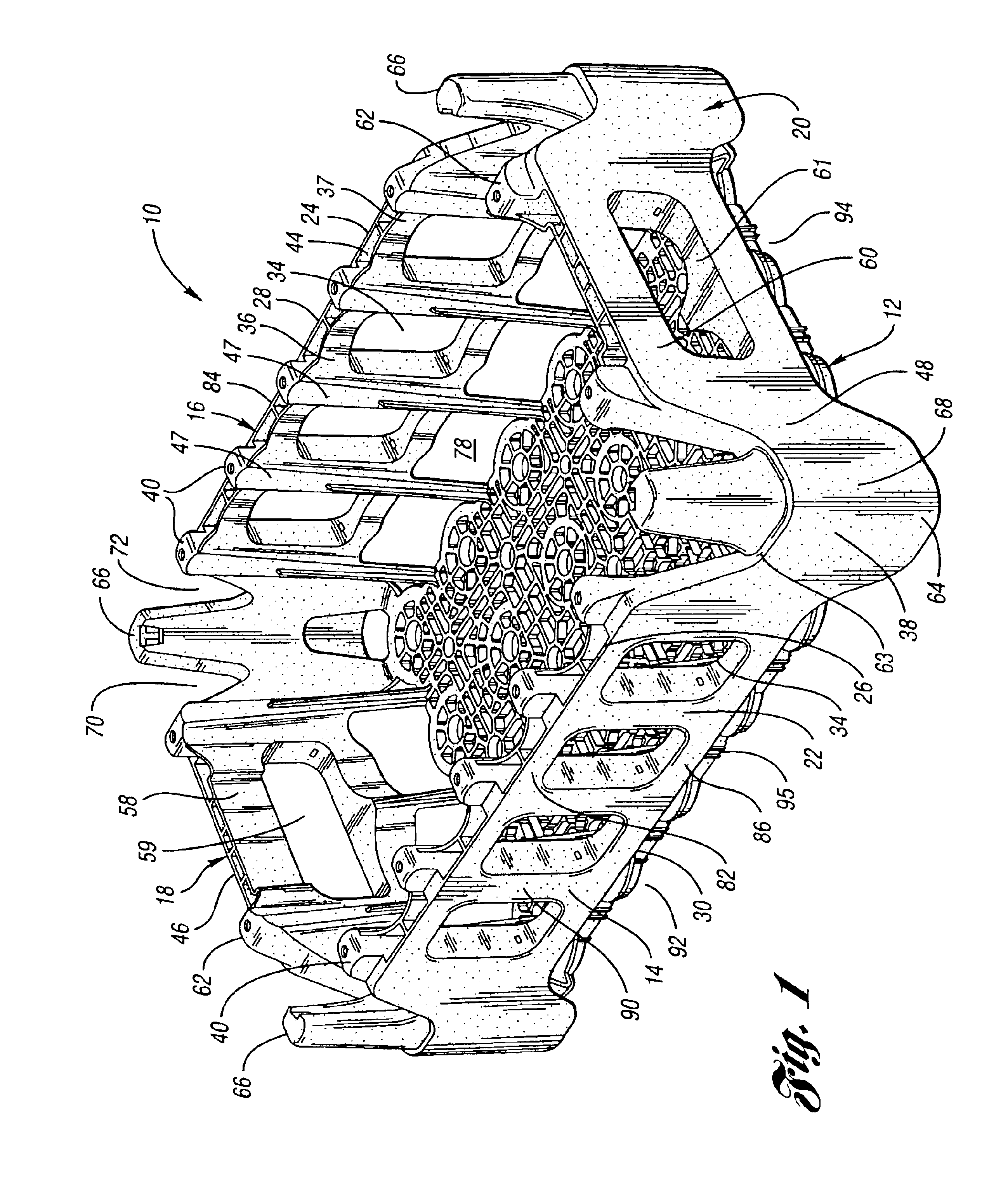
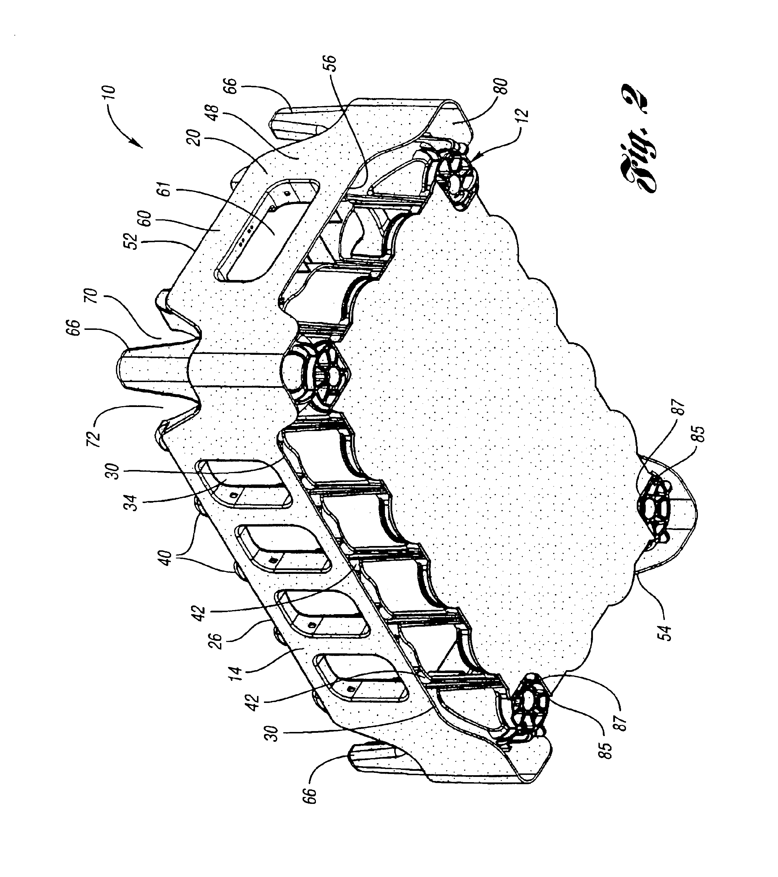
[0037]With references to FIGS. 1-8 of the drawings, illustrated is a first embodiment of a bottle crate 10 according to the present invention. Crate 10 may also be referred to as a tray, container or case, and is formed of a plastic material and preferably a thermoplastic material. Crate 10 includes a floor member or base 12, a first pair of opposed sidewalls 14,16 and a second pair of opposed sidewalls 18,20. For ease of reference, the second pair of opposed sidewalls 18,20 is referred to herein as a pair of end walls 18,20. Sidewalls 14,16, end walls 18,20 and floor member 12 are integrally formed with each other in order to define a compartment therein. As best illustrated in FIGS. 1 and 3, floor member 12 is inwardly offset from the planes of each sidewall 14,16 and end wall 18,20.

[0038]Sidewalls 14,16 include a band member 22,24 defined by an upper edge 26,28 and a lower edge 30,32. In a preferred embodiment, sidewalls 14,16 include one or more openings or windows 34 correspond...


PUM


Abstract

A nestable crate for bottles which includes a floor member and first and second pairs of opposed sidewalls integrally formed with the floor member. Each sidewall includes a side band member which is defined by a centrally disposed upper edge and lower edge. The lower edge is spaced above the floor member by a predetermined distance to define a sidewall nesting area therebelow. The upper and lower edges each contoured downwardly to form a corner band portion having a corner upper edge and corner lower edge, wherein each nesting area matingly receives a corresponding side band member of a crate nested subjacent thereto.

Description

TECHNICAL FIELD[0001]This invention relates to a bottle crate.BACKGROUND ART[0002]Generally, beverage bottles go through a bottle facility and are loaded into trays which are then palletized. A pallet may include multiple layers of trays of a single product, such as soft drinks or beer of the same brand. Trays in successive layers are stacked or cross-stacked on top of each other, with the bottles bearing most of the load of the above-stacked trays. These bulk pallets are then typically stored in a warehouse for shipping to retailers.[0003]One recent advance in the distribution area is a use of a product handling device known as the Tygard Claw® manufactured by Tygard Machine and Manufacturing Company of Pittsburgh, Pa. The Tygard Claw can be installed to the front or the side of a conventional fork lift carriage, and enables a distributor to pick from a bulk pallet of product one layer at a time. Briefly, the Tygard Claw is a large clamping device with four individual walls that ap...

Claims


Application Information

Patent Timeline
Patent Type & Authority Patents(United States)
IPC IPC(8): B65D1/22B65D21/02
CPCB65D1/22B65D21/0212B65D2501/24019
Inventor KOEFELDA, GERALD R.APPS, WILLIAM P.
Owner REHRIG PACIFIC CO INC
Learn More