Bioptics bar code reader

a bar code reader and bioptic technology, applied in the field of dataform reading, can solve the problems of no presentation or slot scanners available in the market today that can read two-dimensional bar codes, and achieve the effect of improving the slot scanner

Inactive Publication Date: 2005-05-31
SYMBOL TECH LLC
View PDF28 Cites 161 Cited by
  • Summary
  • Abstract
  • Description
  • Claims
  • Application Information

AI Technical Summary

Benefits of technology

[0006]The main object of the present invention is to improve the slot scanners that are presently available.

Problems solved by technology

Moreover, although two-dimensional bar codes have been increasing in use, there are currently no presentation or slot scanners available in the market today that can read a two-dimensional bar code from two sides of a package.

Method used


Image

  • Bioptics bar code reader
  • Bioptics bar code reader
  • Bioptics bar code reader

Examples


Embodiment Construction

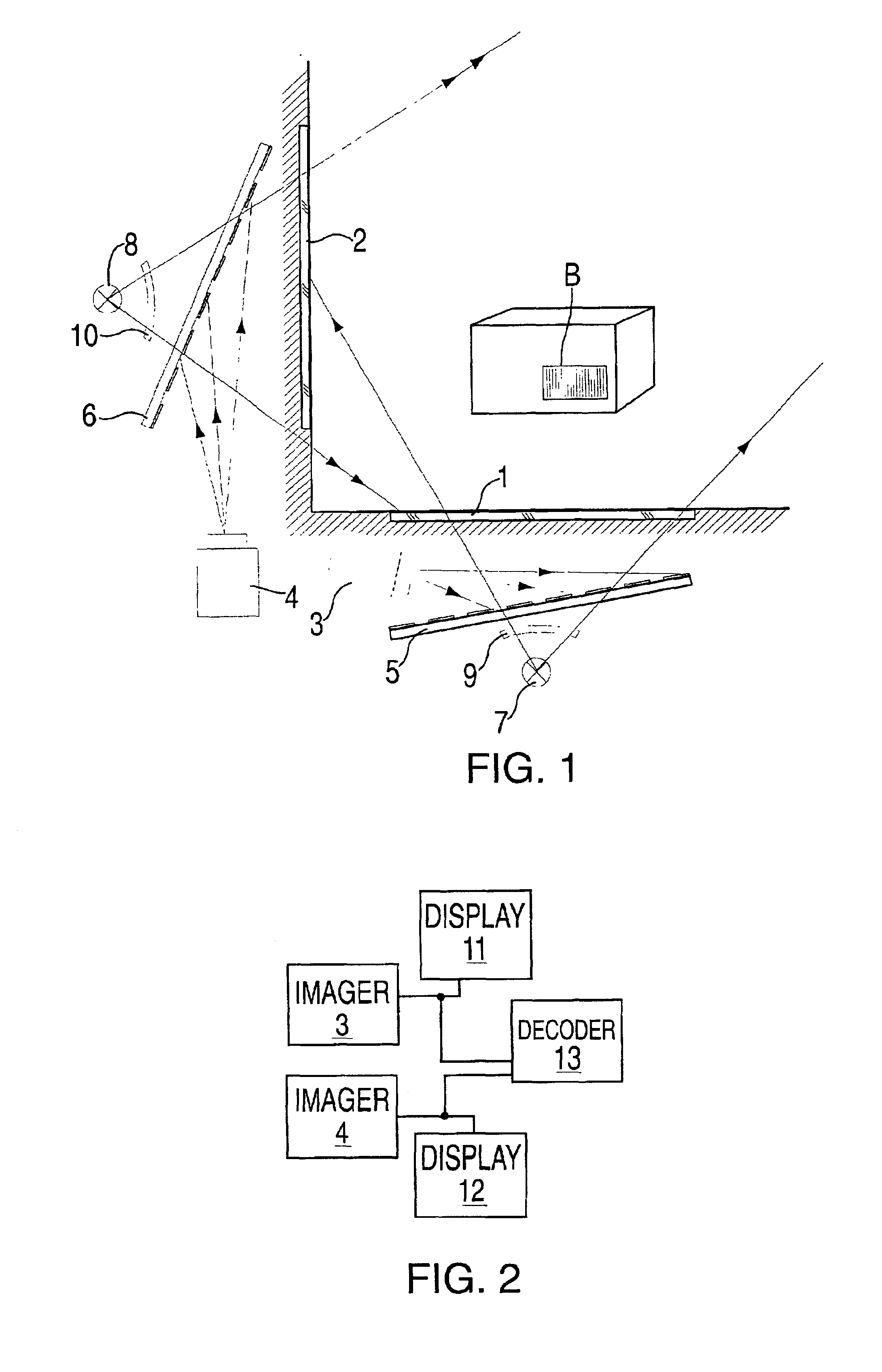
[0017]Referring now to FIGS. 1 and 2, a first embodiment of the bioptics scanner according to the present invention is disclosed.

[0018]In a slot and / or presentation mode scanner, there are two windows 1 and 2 which are at an angle to each other. Although the windows 1 and 2 are at a 90° angle in FIG. 1, other angles can be used. In FIG. 1, window 1 is a horizontal window and window 2 is a vertical window, however, other orientations can also be used within the scope of the invention.

[0019]Behind the windows 1 and 2 are two dimensional array cameras 3 and 4 respectively which are positioned with regard to mirrors 5 and 6 so that their fields of view cover a three-dimensional space where a bar code B can be presented on a three-dimensional object or an identification document, such as a coupon, might be presented. Mirrors 5 and 6 are stationary mirrors which reflect light from the bar code B onto imagers 3 and 4 respectively.

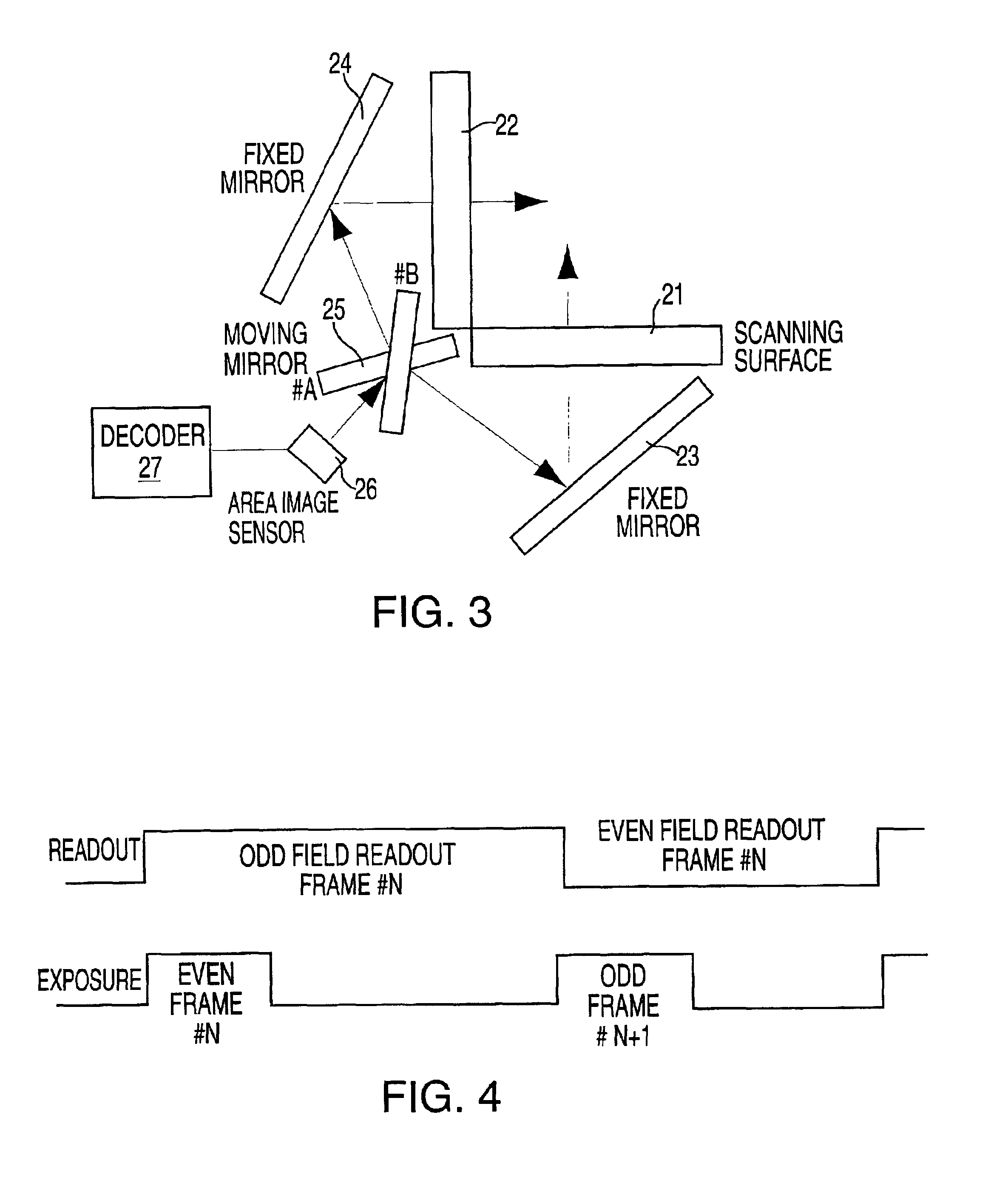
[0020]In order to improve the depth of focus of the imagers ...


PUM


Abstract

A bioptics bar code reader has first and second windows disposed at an angle to each other, a first imager for the first window and a second imager for the second window and first and second optics for directing light from a bar code in a reading area between the windows to the first and second imagers. The two imagers each obtain an image of the bar code in the reading area.

Description

CROSS REFERENCE TO RELATED APPLICATIONS[0001]This application claims priority to U.S. Prosvisional Application No. 60 / 204.689 filed May 17, 2000.BACKGROUND OF THE INVENTION[0002]The present invention relates to the reading of dataforms, such as bar codes, by the use of imagers in slot or presentation mode scanners.[0003]The reading of bar codes by imagers is known, and imagers, such as charge coupled detector (CCD) arrays or CMOS sensors, have been disclosed in U.S. Pat. No. 5,319,181, the disclosure of which is incorporated herein by reference. Such imagers are also referred to as cameras, sensors and the like.[0004]It is proposed that the use of two images of the same bar code from two different views will aid in the speed and reliability of decoding bar codes which have been captured as an image in an imager.[0005]Moreover, although two-dimensional bar codes have been increasing in use, there are currently no presentation or slot scanners available in the market today that can re...

Claims


Application Information

Patent Timeline
Patent Type & Authority Patents(United States)
IPC IPC(8): G06K7/10
CPCG06K7/1096G06K7/10693G06K7/10
Inventor KRICHEVER, MARKPATEL, MEHUL
Owner SYMBOL TECH LLC
Why Eureka
Try Eureka