Stackable transmission line hanger

a technology of transmission line and hanger, which is applied in the field of transmission lines, can solve the problems of large amount of auxiliary hardware, inconvenient installation, and inability to accommodate a limited range of cable diameters in the hanger that includes a hinge section

Inactive Publication Date: 2005-05-31
COMMSCOPE TECH LLC
View PDF91 Cites 78 Cited by
  • Summary
  • Abstract
  • Description
  • Claims
  • Application Information

AI Technical Summary

Problems solved by technology

A considerable amount of installation time is required, first to attach the large number of hangers to the bridge and the tower and then to clamp the transmission line within the hangers.
In addition, a large amount of auxiliary hardware (e.g., screws, bolts, nuts, and washers) is required, along with the hangers themselves.
Cable hangers that include a hinge section can only accommodate a limited range of cable diameters.
This makes the attachment section rigid and non-compliant which makes installation of such hangers difficult, especially where a large diameter cable is being installed on a tower or where the weather conditions limit manual dexterity, e.g., cold weather.
The use of tools is undesirable, especially where a transmission line is being installed on a tall tower.
Furthermore, some prior hanger designs do not adequately prevent longitudinal movement of the cable with respect to the hangers.
Hangers without mechanisms for penetrating or biting into the cable jacket cannot prevent longitudinal movement of the cable because the frictional coefficient between the metal hanger and the plastic cable jacket is very low.
In addition, the cable jacket can “cold flow” which reduces the holding force of the cable hanger over time, resulting in cable slippage.
One drawback of current stackable hanger designs, however, is that a considerable amount of installation time is required to attach the two hanger halves around the transmission line(s) and the hanger assembly to the supporting structure.
Moreover, when subsequent transmission lines must be added to accommodate one or more new antennas, the existing two piece stackable hanger assembly has to be unassembled to add another hanger thereto.
The installation of one or more transmission lines along a supporting structure is often a difficult and time-consuming operation because of the large amount of auxiliary hardware required to install some prior hangers and / or the necessity to remove an assembled hanger to add an additional transmission line.

Method used


Image

  • Stackable transmission line hanger
  • Stackable transmission line hanger
  • Stackable transmission line hanger

Examples


Embodiment Construction

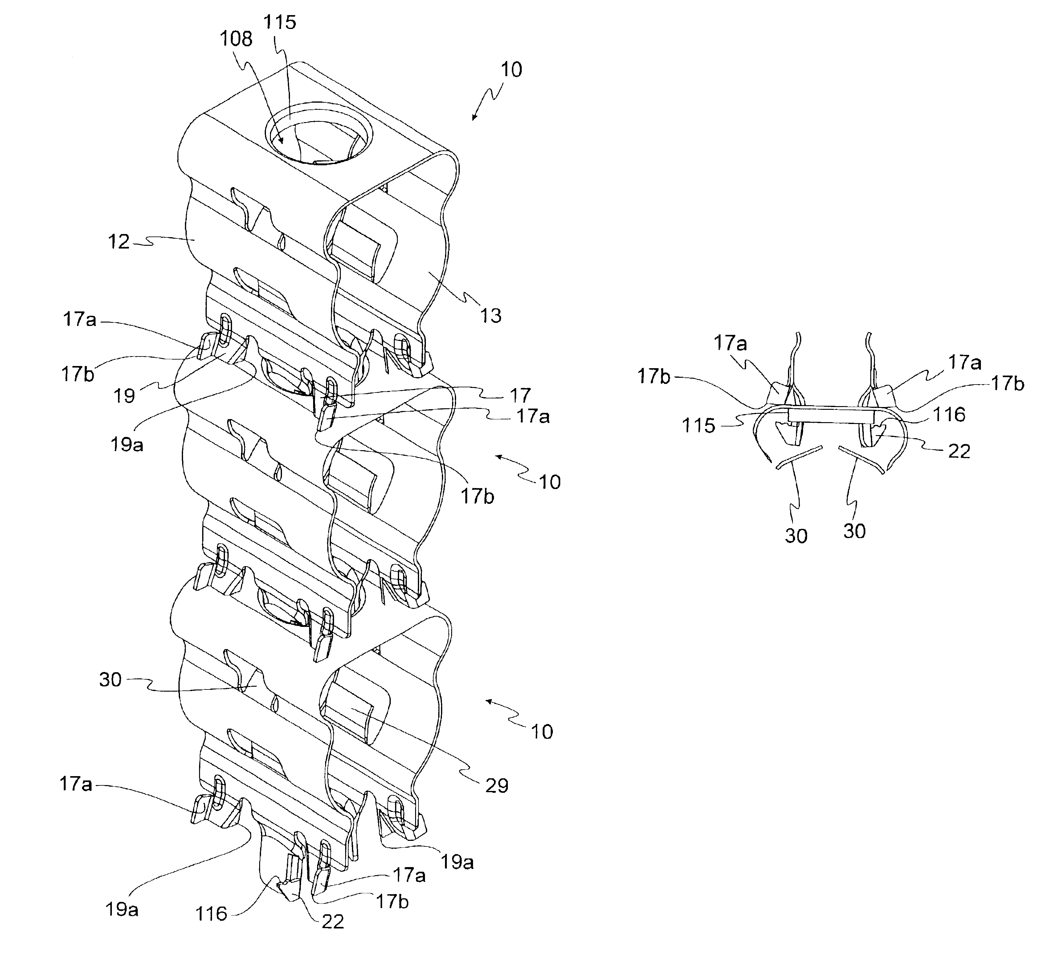
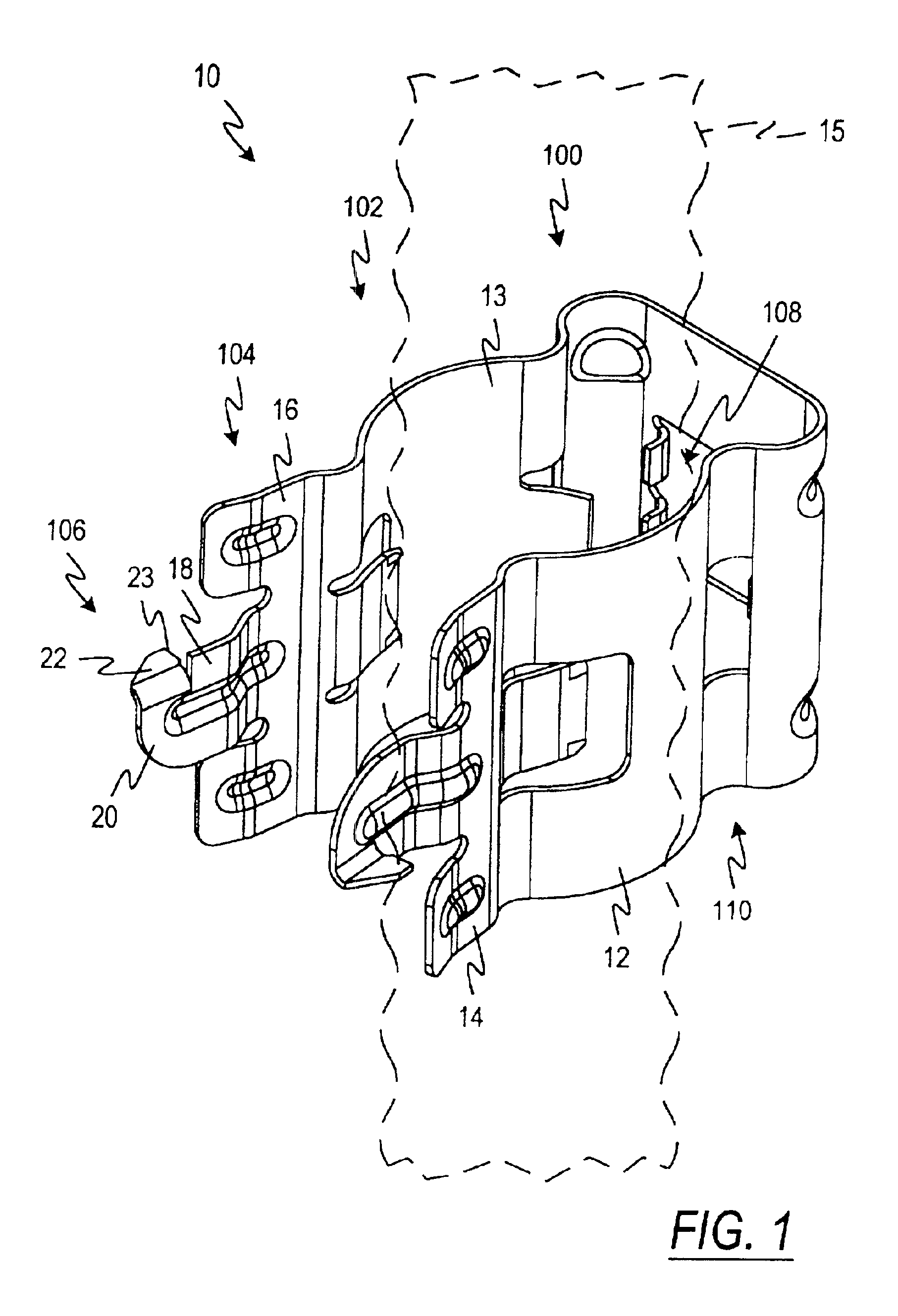
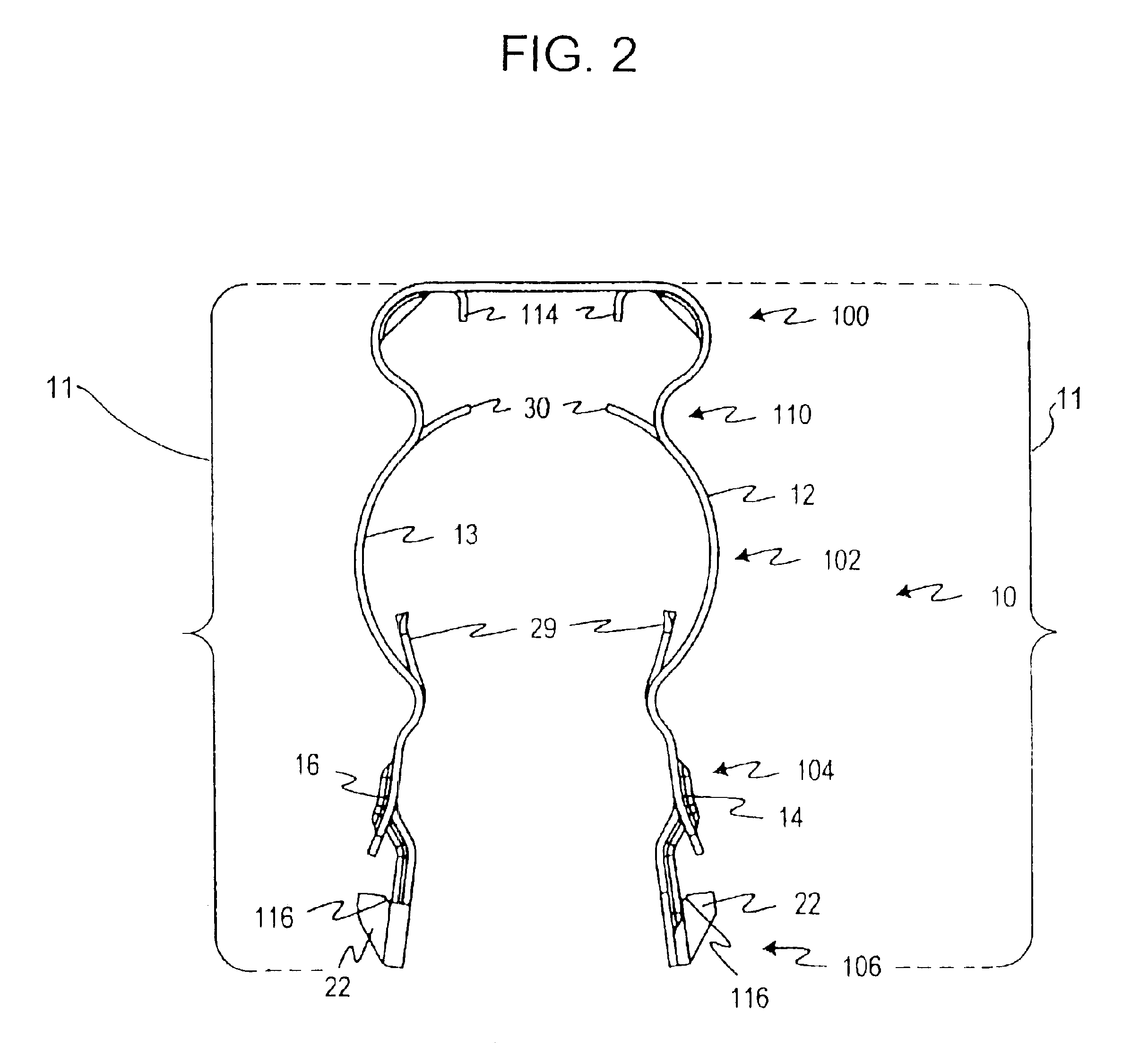
[0033]It has been discovered that multiple transmission lines can be efficiently and inexpensively supported by using a one piece, stackable transmission line hanger 10 according to one embodiment of the present invention. A one piece or unitary hanger is less expensive to produce and more reliable than hangers composed of several pieces. A stackable hanger having two or more pieces that are, for example, welded together, however, would function the same as the unitary hanger described herein.

[0034]In one aspect, a stackable transmission line hanger is provided for securing one or more transmission lines to a supporting structure. Each such hanger includes a transmission line retention section for accommodating a transmission line and a mounting section extending from the transmission line retention section. The mounting section supports a mounting hole disposed therein. The hanger 10 is generally U-shaped and includes arms 11. The transmission line retention section includes a firs...


PUM


Abstract

In one aspect, a stackable transmission line hanger is provided for securing one or more transmission lines to a supporting structure. Each such hanger includes a transmission line retention section for accommodating a transmission line and a mounting section extending from the transmission line retention section, the mounting section including a mounting hole disposed therein. The transmission line retention section includes a first leg and a second leg extending therefrom, the first and second legs allowing the hanger to accommodate various sizes of transmission lines. The first and second legs each include a locking barb configured to lock against an attachment surface.

Description

CROSS-REFERENCE TO RELATED APPLICATION[0001]This application is a continuation-in-part of U.S. patent application Ser. No. 09 / 430,496 filed Oct. 29, 1999, now issued as U.S. Pat. No. 6,354,543 on Mar. 12, 2002, which is a continuation-in-part of U.S. patent application Ser. No. 09 / 229,843 filed Jan. 12, 1999, now issued as U.S. Pat. No. 6,161,804 on Dec. 19, 2000.FIELD OF THE INVENTION[0002]This invention relates generally to transmission lines and, in particular, to stackable transmission line hangers for supporting one or more transmission lines for an antenna system.BACKGROUND OF THE INVENTION[0003]Transmission line hangers are used to support transmission lines. Generally, a transmission line is inserted into a transmission line hanger which is then attached to a supporting structure. The most extensive use of hangers is in connection with coaxial cables, such as those disclosed in U.S. Pat. No. 5,334,051 to Devine et al. and U.S. Pat. No. 5,167,533 to Rauwolf. Coaxial cables ar...

Claims


Application Information

Patent Timeline
Patent Type & Authority Patents(United States)
IPC IPC(8): F16L3/12H01P1/00H02G7/05H02G3/30
CPCF16L3/12H02G3/30H01P1/00
Inventor KORCZAK, RICKPASKE, JAMIE M.
Owner COMMSCOPE TECH LLC
Why Eureka
Try Eureka