Linkage assembly for operating one or more latches

a technology of latches and links, applied in the field of latches, can solve problems such as affecting the design of latches, affecting the operation of latches, and affecting the operation of latches, and achieve the effects of reducing the difficulty of design, avoiding bending, and avoiding bending

Inactive Publication Date: 2005-05-31
THE EASTERN COMPANY
View PDF63 Cites 34 Cited by
  • Summary
  • Abstract
  • Description
  • Claims
  • Application Information

AI Technical Summary

Benefits of technology

[0025]The present invention provides an linkage assembly that includes an arm-movement coordinating element to overcome the foregoing and other drawbacks of the prior art. A linkage assembly is provided that offers coordinated movement of its arms in unison while retaining much of the same general configuration and the compactness of s

Problems solved by technology

The result of this uncoordinated return movement of the arms may be that, when the push button actuator is depressed to engage and pivot the arms, one of the arms may be engaged by the actuator well in advance of when the other arm is engaged by the actuator.
If the independently movable arms fail to move in unison in a coordinated manner, this can result in inconsistent operation that may bring with it impositions of larger than intended forces on the elements of the linkage assemblies that may eventually cause binding, jamming, wear and/or premature operational failure.
The absence of any arm-interconnecting element in the linkage assemblies of the Eberhard and Tri/Mark Patents to coordinate the movements of the arms of these assemblies has presented a dilemma to designers that has not been easy to resolve without significantly increasing the overall dimensions of the linkage assemblies.
Because the linkage assemblies of the Eberhard and Tri/Mark Patents are already quite compact and already are designed to occupy a minimum of space, adding components to these assemblies to coordinate the movement of the first and second arms of these assemblies has provided a daunt

Method used


Image

  • Linkage assembly for operating one or more latches
  • Linkage assembly for operating one or more latches
  • Linkage assembly for operating one or more latches

Examples


Embodiment Construction

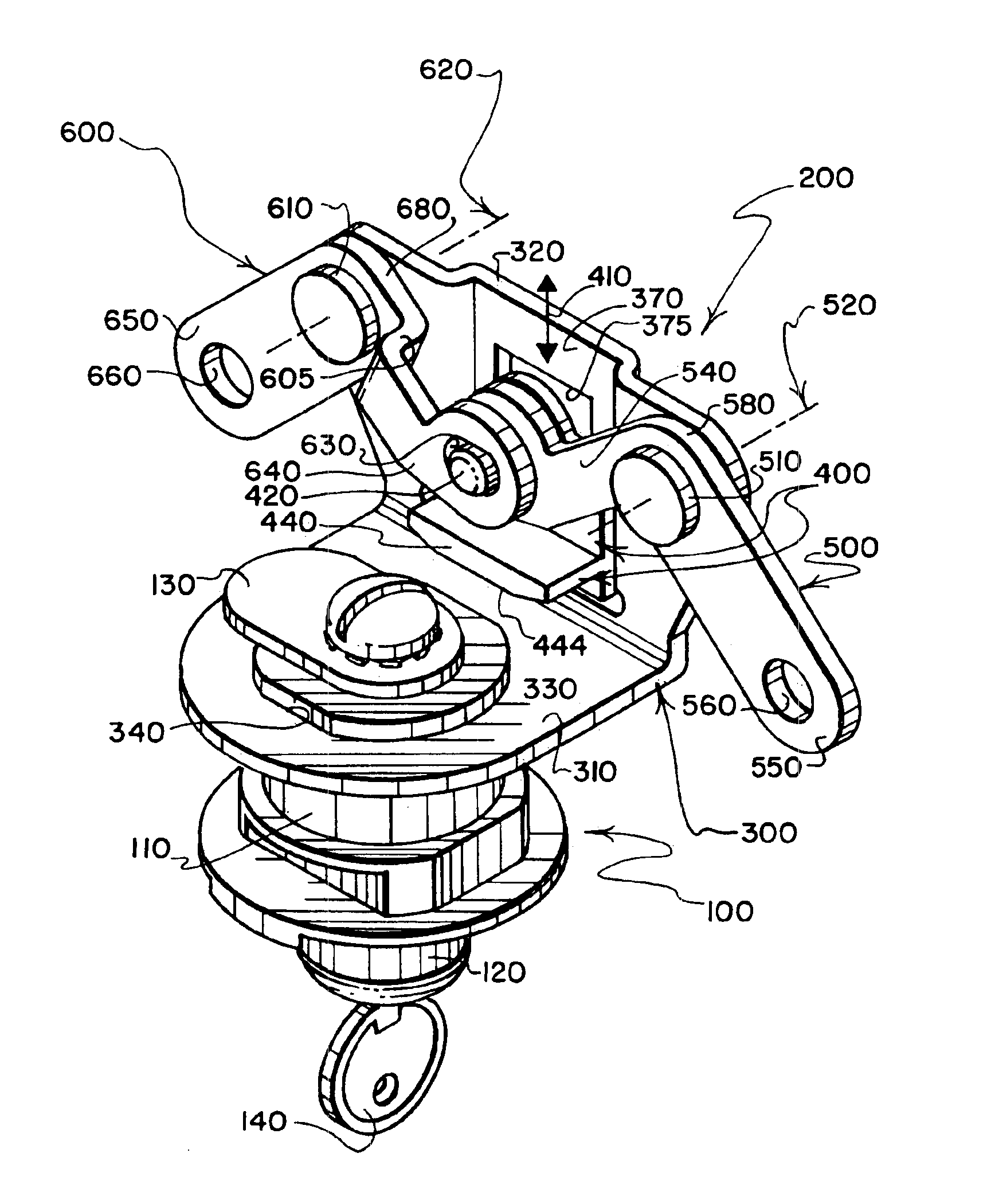
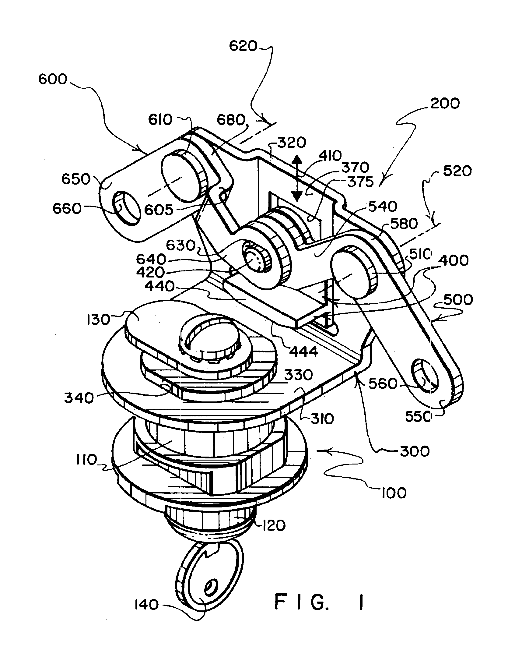
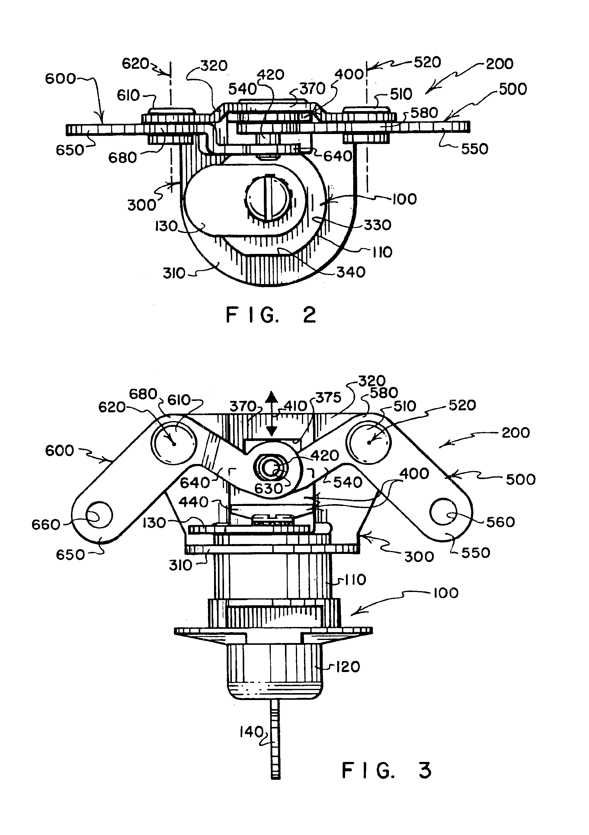
[0062]Reference is made the aforementioned Push Button Operator Utility Case (application Ser. No. 09 / 698,416, the disclosure of which is incorporated herein by reference) which, at FIGS. 12-23, discloses a push button operator assembly 2132 with a linkage assembly 2500 connected thereto and having a frame 2510 that pivotally supports a pair of J-shaped arms 2600 with inner end regions 2610 having edges that are directly engaged by an actuator cam 2172 of the push button operator assembly 2132 for moving a pair of latch connected links that are indicated schematically by arrows 2900 and 2901. The linkage assembly of the present invention is substitutable for the linkage assembly 2500 disclosed in the referenced Push Button Operator Utility Application to serve the same functions as are served by the linkage assembly 2500. The linkage assembly of the present invention also may serve other useful functions such as providing a connection point for an emergency release cable, as will be...


PUM


Abstract

A linkage assembly includes a frame, an arm movement coordinating member slidably supported by the frame, and a pair of arms pivotally connected to the frame and connected to the coordinating member to ensure that the arms pivot in unison when the coordinating member is slided relative to the frame by depressing a push button that is connected to the frame for translation relative thereto. Either of the arms can be link-connected to a latch assembly for operating either a single latch assembly or for concurrently operating a pair of latch assemblies in response to depression of the push button. An optional emergency release cable may connect with the arm movement coordinating member to facilitate latch operation from inside a tonneau cover of a pickup truck or the like that is held closed by the latch or latches.

Description

REFERENCE TO PROVISIONAL APPLICATION[0001]This application claims the benefit of U.S. provisional application Ser. No. 60 / 377,117 entitled LINKAGE ASSEMBLY FOR OPERATING ONE OR MORE LATCHES filed May 2, 2002 by Lee S. Weinerman et al the disclosure of which is incorporated herein by reference.CROSS-REFERENCE TO RELATED APPLICATIONS[0002]The present application is a continuation-in-part of one utility application, and also is a continuation-in-part of each of five design applications, namely:[0003]1) Utility application Ser. No. 09 / 698,416 filed Oct. 27, 2000 now U.S. Pat. No. 6,454,320 by Lee S. Weinerman et al entitled PUSH BUTTON OPERATORS FOR LATCHES AND LOCKS, AND LOCKING SYSTEMS EMPLOYING LOCKABLE PUSH BUTTON OPERATORS, referred to herein as the “Push Button Operator Utility Case” or as the “Eberhard Patent”);[0004]2) Design application Ser. No. 29 / 160,445 filed May 10, 2002 now U.S. Design Pat. No. D471,427 by Lee S. Weinerman et al entitled LINKAGE ASSEMBLY FOR USE WITH PUSH ...

Claims


Application Information

Patent Timeline
IPC IPC(8): E05B13/00E05B13/10E05C3/16E05C3/00
CPCE05B13/105E05C3/162E05B13/101Y10S70/20Y10S292/37Y10T292/0841Y10T292/57Y10T292/0855Y10T70/5102Y10T70/5761Y10T70/7576
Inventor WEINERMAN, LEE S.ARTHURS, SCOTT A.KUMINSKI, ARTHUR J.
Owner THE EASTERN COMPANY
Why Eureka
Try Eureka