
Thermistor temperature sensor

a technology of thermistor elements and temperature sensors, applied in the field of temperature sensors, can solve problems such as the case of tensile stress applied to the electrode wires, and achieve the effect of preventing the breaking improving the vibration resistance of the electrode wires of the thermistor elements

Inactive Publication Date: 2005-05-31
DENSO CORP
View PDF18 Cites 49 Cited by
  • Summary
  • Abstract
  • Description
  • Claims
  • Application Information

AI Technical Summary

Benefits of technology

[0008]Accordingly, the present invention has been developed in view of the above problem, and an object thereof is to provide a temperature sensor in which a thermistor element is supported on a wiring for taking out a thermistor signal to the outside by joining electrode wires of the thermistor element to the wiring, so that the vibration resistance of the electrode wires of the thermistor element is improved so as to prevent breaking of the electrode wires.
[0010]According to the present invention, since the electrode wires are held by the insulator, even in case vibrations are applied to the sensor, the electrode wires are prevented from vibrating, whereby the vibration resistance of the electrode wires is improved. In addition, since the insulator is a molded body and is not bonded to the electrode wires, there is no case where a tensile stress is applied to the electrode wires from the insulator when the temperature becomes high.

Problems solved by technology

In addition, since the insulator is a molded body and is not bonded to the electrode wires, there is no case where a tensile stress is applied to the electrode wires from the insulator when the temperature becomes high.

Method used


Image

  • Thermistor temperature sensor
  • Thermistor temperature sensor
  • Thermistor temperature sensor

Examples


Embodiment Construction

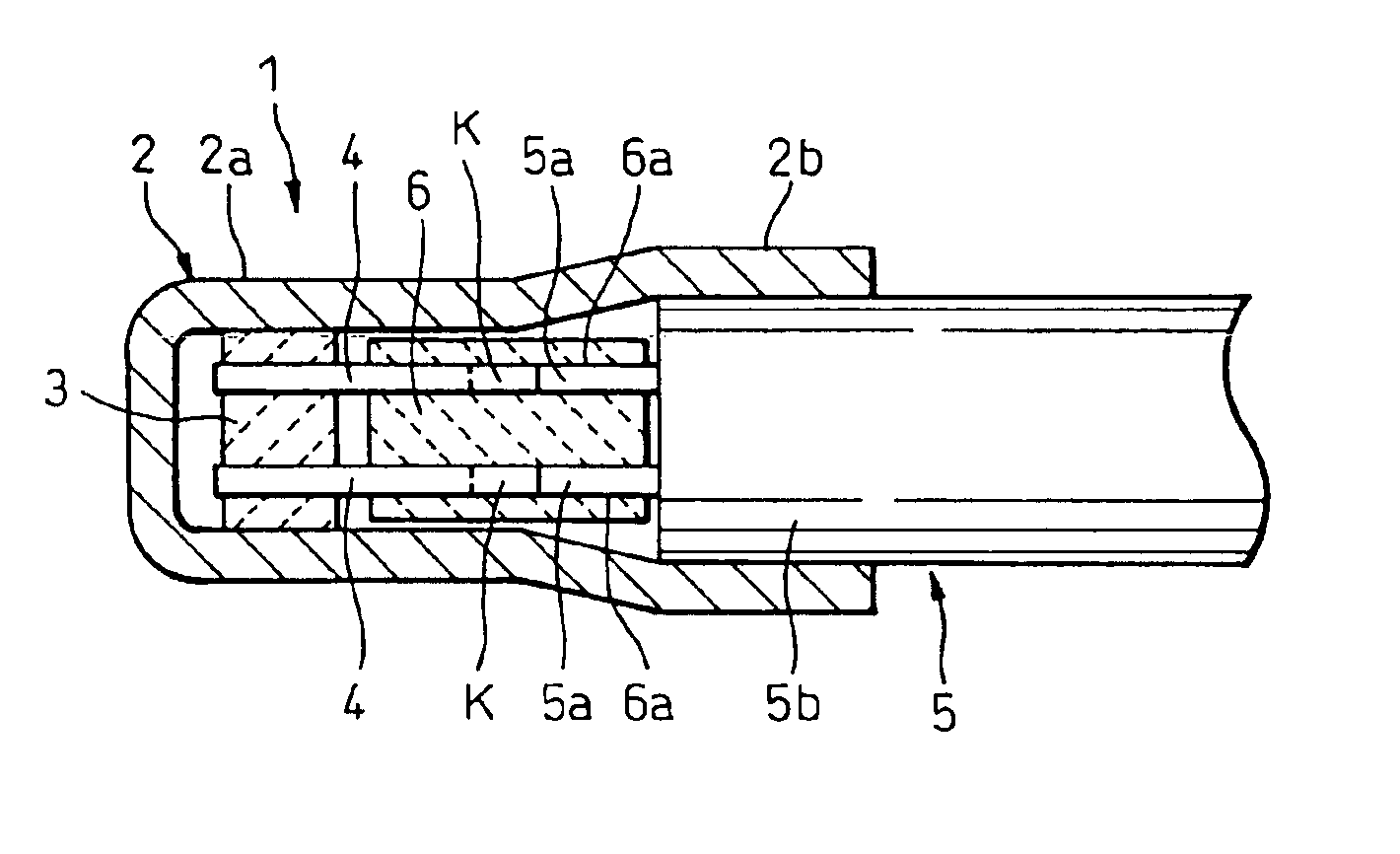
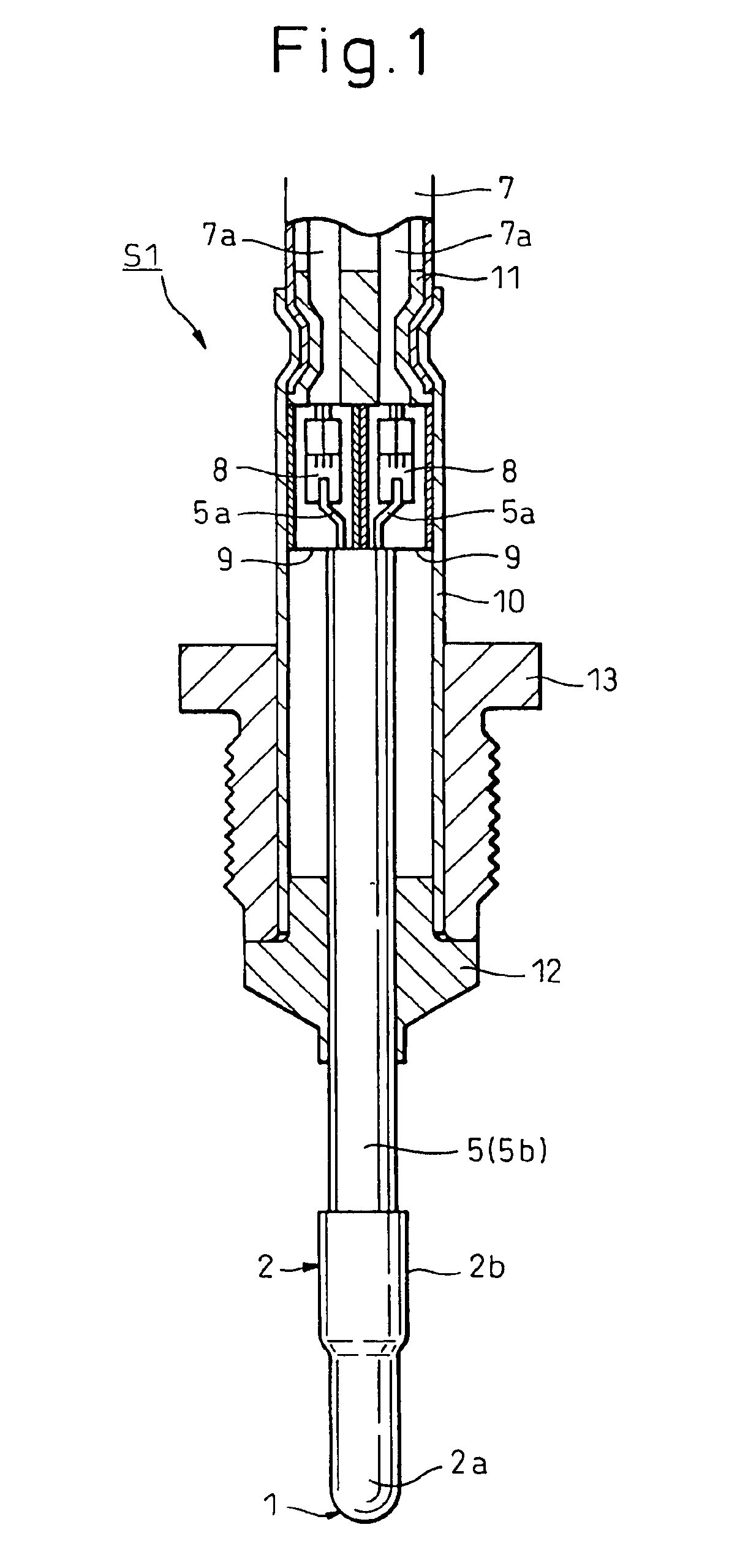
[0020]The present invention will be described below based on embodiments illustrated in the accompanying drawings. FIG. 1 shows the overall construction of a temperature sensor S1 according to an embodiment of the present invention, in which the temperature sensor is shown in cross section except for a temperature-sensing portion 1 thereof. In addition, FIG. 2 is an enlarged sectional view of the temperature-sensing portion 1 shown in FIG. 1. The temperature sensor S1 is mounted, for example, in an exhaust system of an automobile for use as an exhaust gas temperature sensor.

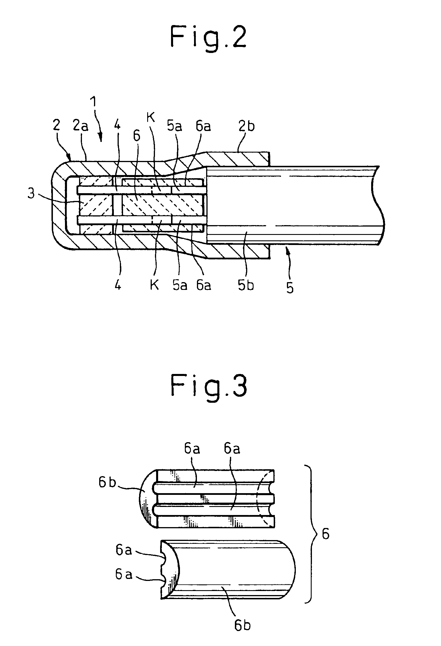
[0021]Firstly, referring mainly to FIG. 2, the temperature-sensing portion 1 will be described. Reference numeral 2 denotes a metallic cover made of a metal such as stainless steel which is superior in heat resistance, and in this embodiment, the metallic cover 2 is formed into a stepped cylindrical shape having a bottom portion at one end and an opening at the other end thereof. A thermistor element 3 is housed ...


PUM


Abstract

An insulator 6 for holding electrode wires 4 is provided between a thermistor element 3 and a sheathed pin 5 which is a wiring, and the electrode wires 4, which are inserted into hole portions 6a of the insulator 6, are held therein not bonded to the insulator, whereby the vibration resistance of the electrode wires of the thermistor element is improved so that breaking of the electrode wires is prevented.

Description

BACKGROUND OF THE INVENTION[0001]1. Field of the Invention[0002]The present invention relates to a temperature sensor in which a thermistor element is supported on a wiring (a sheathed pin) for taking out a thermistor signal to the outside by joining electrode wires of the thermistor element to the wiring.[0003]2. Description of the Related Art[0004]Conventionally, a temperature sensor of this kind is proposed in Japanese Unexamined Patent Publication (Kokai) No. 2000-88673. The temperature sensor comprises a thermistor element, electrode wires led from the thermistor element for detecting a thermistor signal and a wiring (a sheathed pin) for taking out the thermistor signal so detected to the outside, and in the temperature sensor, the thermistor element is supported on the wiring by joining the electrode wires to the wiring.[0005]Incidentally, the aforesaid conventional temperature sensor is constructed such that a ceramic molded body is disposed around an outer circumference of t...

Claims


Application Information

Patent Timeline
IPC IPC(8): G01K7/22G01K7/16H01C7/04
CPCG01K7/22
Inventor KURANO, ATSUSHI
Owner DENSO CORP
Learn More