Grinding apparatus for blending defects on turbine blades and associated method of use

a technology of grinding apparatus and turbine blade, which is applied in the direction of mechanical equipment, machines/engines, manufacturing tools, etc., can solve the problems of high cost, time-consuming and expensive procedures, and often damaged gas turbine engines, typically mounted on the wing of aircra

Inactive Publication Date: 2005-05-31
MOELLER DIETER +2
View PDF15 Cites 827 Cited by
  • Summary
  • Abstract
  • Description
  • Claims
  • Application Information

AI Technical Summary

Benefits of technology

[0015]In use, a defect on a turbine blade may be blended or smoothed using the grinding apparatus of the present invention. The first step in utilizing the grinding apparatus of the present invention is to couple a commercially available endoscope to the grinding tool. This is accomplished by passing a portion of the endoscope, including the lens end, through the base of the grinding tool, through the support tube of the grinding tool and out an opening in the support tube. When coupled to a light source, the endoscope enables the operator to view inside the engine casing.

Problems solved by technology

Such gas turbine engines, typically mounted on the wing of an aircraft, are frequently damaged by foreign objects, such as sand particles, stones, or other objects ingested by the engine during takeoff.
These foreign objects ingested by the air turbine engine often cause generally V-shaped nicks or chips on impact along the leading edge of the affected turbine blades.
This procedure is time-consuming and extremely expensive.
One difficulty with tools using rotary heads is that the rotational speed required to blend the defect is so high that the surface of the turbine blade becomes very hot due to friction.
Because most turbine blades are made of titanium, the integrity of the titanium may be compromised at high temperatures.
The apparatus disclosed in this patent is difficult to use and subject to failure due to the configuration and operation of the apparatus.

Method used


Image

  • Grinding apparatus for blending defects on turbine blades and associated method of use
  • Grinding apparatus for blending defects on turbine blades and associated method of use
  • Grinding apparatus for blending defects on turbine blades and associated method of use

Examples


Embodiment Construction

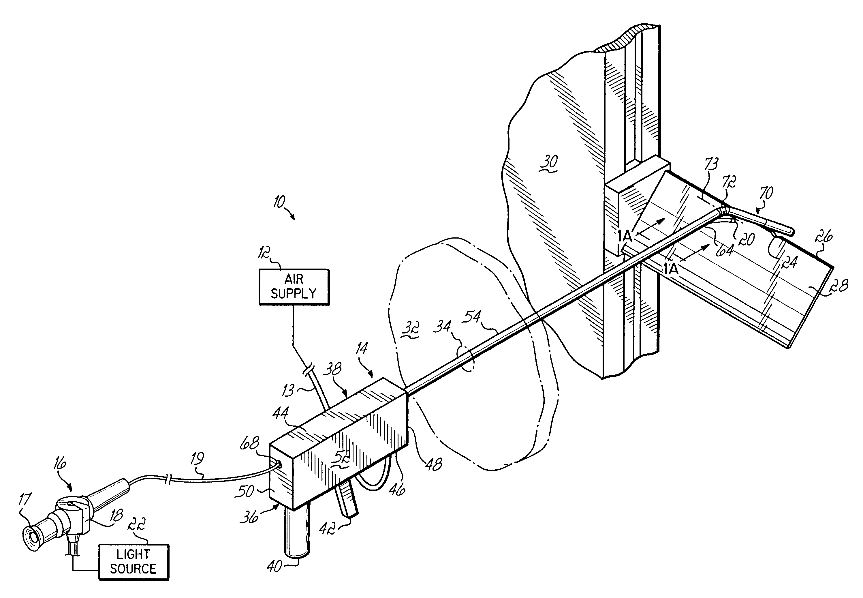
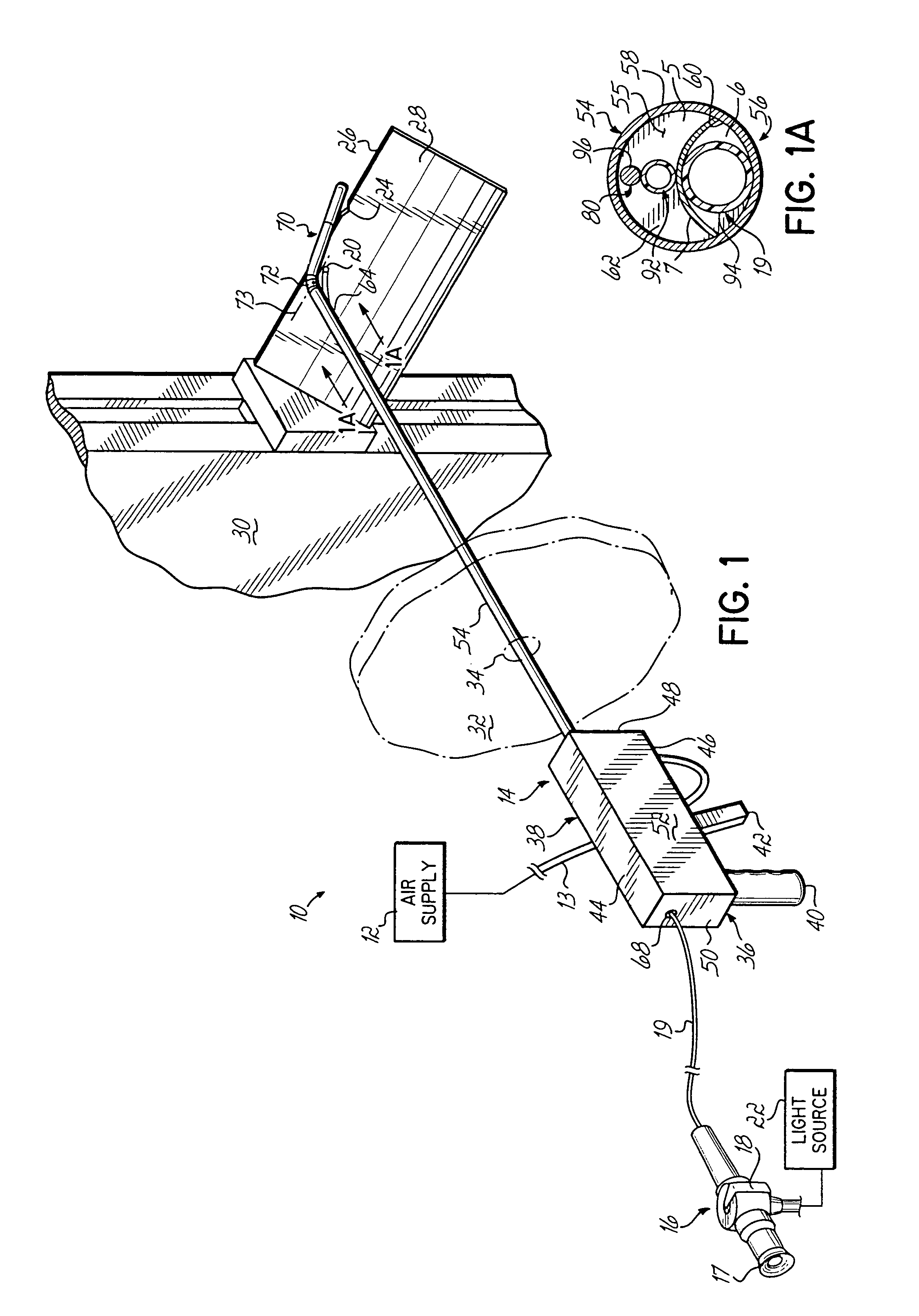
[0026]Referring to the drawings and particularly to FIG. 1, there is illustrated a grinding apparatus 10 including an air supply 12, an air supply line 13 and a grinding tool 14 for use with an endoscope 16. The endoscope 16 has an eyepiece 17 at the end of a tube 19 and an articulated lens end 20 moveable via movement of a lever 18 on the eyepiece 17, as is known in the art. Any other sort of viewer such as a video viewer may be used in place of the eyepiece 17 to view or display data. Preferably, the endoscope 16 is used with a light source 22. Although one type of endoscope is illustrated and described, the grinding apparatus 10 may be used with many different types of endoscopes.

[0027]The grinding apparatus 10 of the present invention is used for blending or retouching a defect, notch or nick 24 along the leading edge 26 of a turbine blade 28 secured to a drum 30 (only partially shown) in a manner known in the art. The drum 30 and turbine blades 28 attached thereto are mounting ...


PUM

PropertyMeasurementUnit
angleaaaaaaaaaa
movementaaaaaaaaaa
frequencyaaaaaaaaaa

Abstract

A grinding apparatus for use with an endoscope for viewing and blending defects on a turbine engine blade is provided. In one preferred embodiment air pulses from an air supply cause a grinding head on the end of a grinding tool to reciprocate at a predetermined speed. The position of the grinding head is fixed via the operator via a trigger on the grinding tool which articulates an outer portion of a support tube of the grinding tool. In another preferred embodiment, fluid is used to reciprocate the grinding head.

Description

FIELD OF THE INVENTION[0001]The present invention relates to apparatus for blending defects on turbine blades such as, for example, nicks and notches. More particularly, this invention relates to a grinding apparatus for blending defects on turbine blades using an endoscope to view the defects through observation ports in an engine casing.BACKGROUND OF THE INVENTION[0002]Conventional gas turbine engines, such as those used in aircraft, are enclosed in an engine casing and include a plurality of turbine blades secured to a drum. Such gas turbine engines, typically mounted on the wing of an aircraft, are frequently damaged by foreign objects, such as sand particles, stones, or other objects ingested by the engine during takeoff. These foreign objects ingested by the air turbine engine often cause generally V-shaped nicks or chips on impact along the leading edge of the affected turbine blades. The process of replacing a turbine blade is very expensive, so repair in place is desirable ...

Claims


Application Information

Patent Timeline
Patent Type & Authority Patents(United States)
IPC IPC(8): B24B27/00B24B19/00B24B19/14B24B27/027
CPCB24B19/14F01D5/005B24B27/027
Inventor MOELLER, DIETERMOELLER, HEINZ D.MOELLER, DAVID B.
Owner MOELLER DIETER
Why Eureka
Try Eureka