
Method of applying a marker element to an implant and an implant provided with a marker element

a technology of marker elements and implants, which is applied in the field of applying a marker element to an implant and an implant provided with a marker element, can solve the problems of high mechanical load on implants, damage to surrounding tissue, and failure to occur in the implanted condition, and achieve the effect of low cost and easy identification

Inactive Publication Date: 2005-05-31
BIOTRONIK MESS UND THERAPIEGERAETE GMBH & CO
View PDF17 Cites 75 Cited by
  • Summary
  • Abstract
  • Description
  • Claims
  • Application Information

AI Technical Summary

Benefits of technology

[0009]The object of the present invention is therefore that of providing a method of the general kind set forth for applying a marker element to an implant as well as an implant of the general kind set forth, which do not suffer from the above-indicated disadvantages or which suffer therefrom at least to a lesser degree and which in particular ensure simple and flexible production.

Problems solved by technology

Both those alternative structures suffer from the disadvantage that the implant is subjected to in part really high mechanical loadings in the region of the opening, in the pressing operation.
That is particularly harmful because it cannot be immediately detected and possibly only causes failure to occur in the implanted condition.
Thus for example in the case of a stent the structure may involve unwanted sharp broken edges which possibly even damage the surrounding tissue.
It will be appreciated that equally the marker element may also come loose from the implant, which is undesirable.
Here, as moreover also in the case of the above-mentioned alternative configurations, there is the disadvantage that the opening and the marker element must be produced with a relatively accurate fit in order to ensure that a sufficient mechanical bond is achieved.
All these variants therefore involve relatively expensive manufacture.
In addition, in all known variants, the amount of freedom in terms of varying the geometry of the marker or the opening is restricted from economic points of view as different respective markers have to be produced for different openings.

Method used


Image

  • Method of applying a marker element to an implant and an implant provided with a marker element
  • Method of applying a marker element to an implant and an implant provided with a marker element
  • Method of applying a marker element to an implant and an implant provided with a marker element

Examples


Embodiment Construction

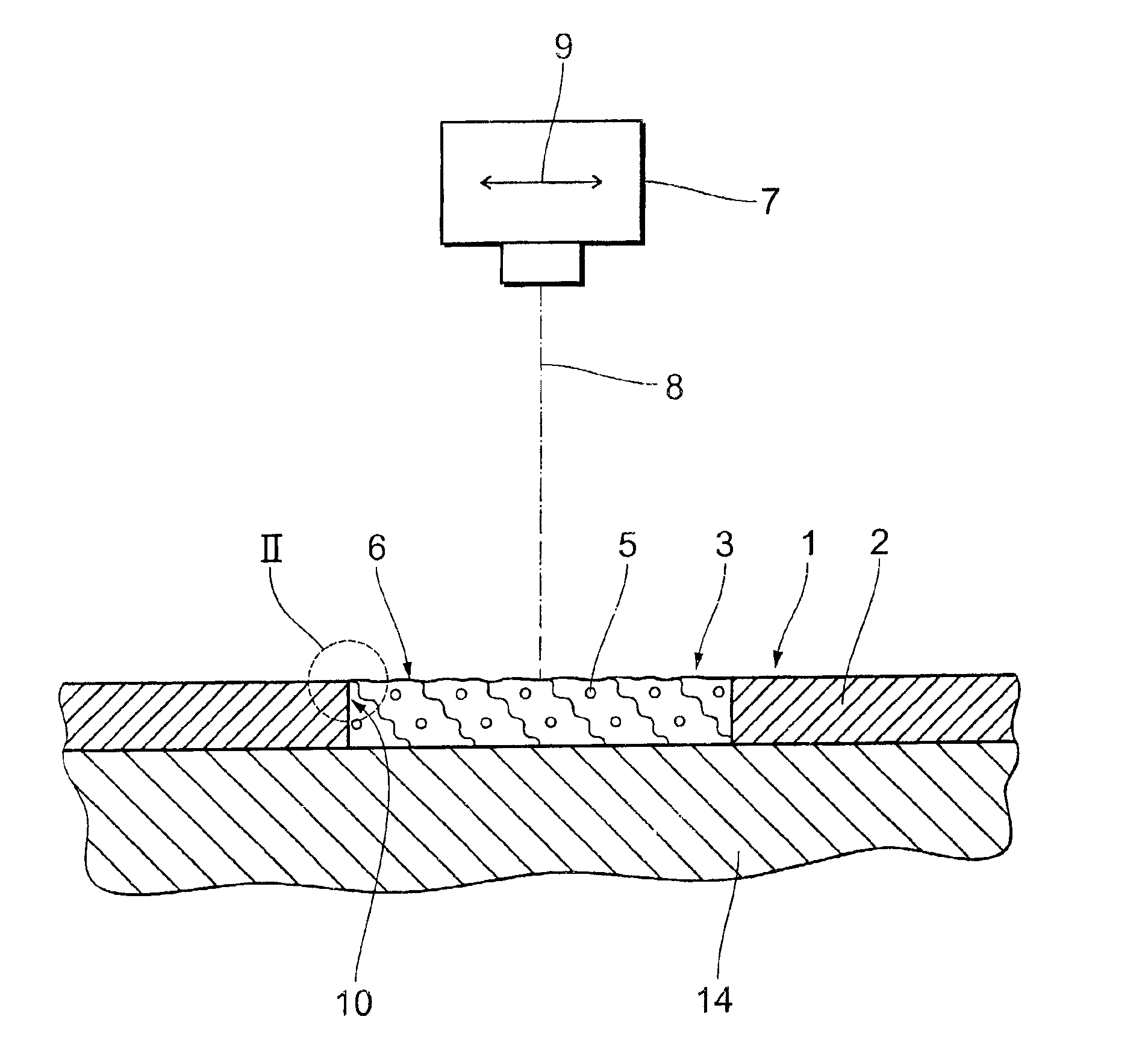
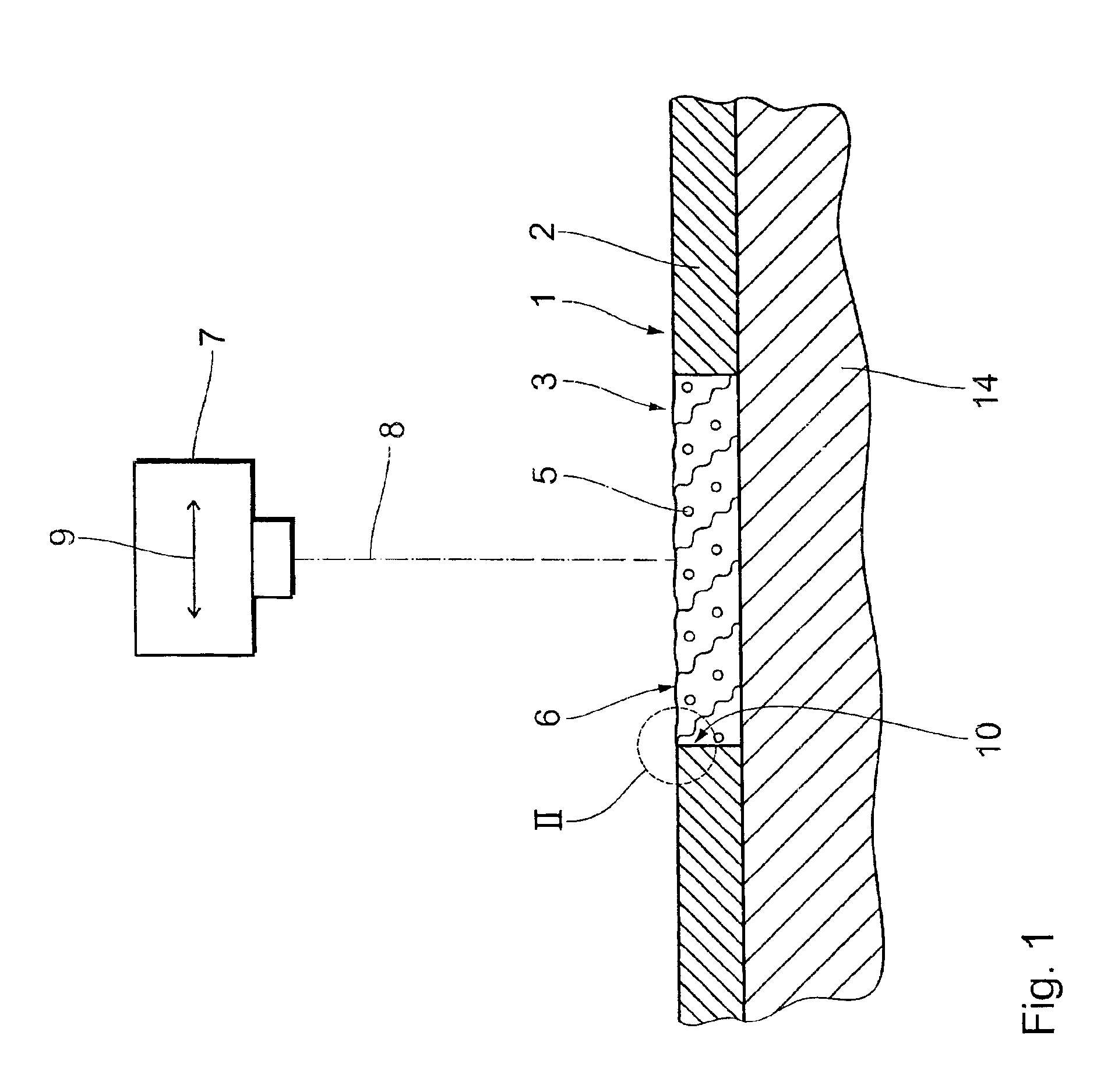
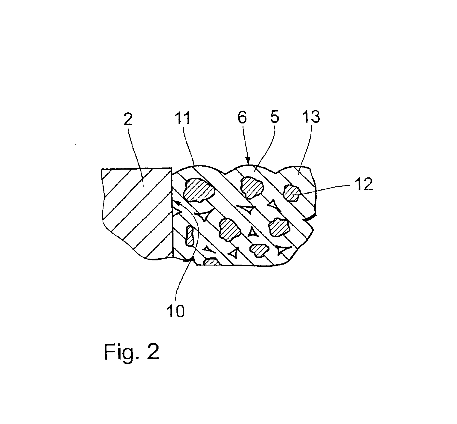
[0034]FIG. 1 shows a diagrammatic partial view in section through an arrangement for carrying out a preferred variant of the method according to the invention, including an implant 1, in the main body 2 of which is provided an opening 3. A hardenable, pourable material mix in the form of a granular material 5 is introduced into the opening 3.

[0035]In the illustrated example the implant is a stent 1 having a tubular main body 2. It will be appreciated however that the invention can also be used in relation to any other implants. It will further be appreciated that in that respect it is possible to use any materials for the main body of the implant. It is only necessary for the flowable or pourable material or material mix to be suited thereto.

[0036]The hardened granular material 5 forms a marker element in the form of an X-ray marker 6. The granular material 5 is hardened in an operation which includes an endothermic step. In that endothermic step so much energy is applied to the gra...


PUM

PropertyMeasurementUnit
Hardeningaaaaaaaaaa
Energyaaaaaaaaaa

Abstract

A method of applying a marker element (6; 6′; 6″; 25; 25′; 26; 28) to an implant (1; 1′; 1″; 1′″; 20; 20′), in particular a stent, intended for implantation in the human or animal body, comprising a main body and an opening (3; 3′; 3″; 3′″; 21; 21′) provided in said main body (2; 2′; 2″; 2′″; 22; 22′) for receiving the marker element (6; 6′; 6″; 25; 25′; 26; 28), wherein to form at least a part of the marker element (6; 6′; 6″; 25; 25′; 26; 28) a hardenable material or material mix is introduced into the opening and hardened therein.

Description

[0001]The present invention concerns a method of applying a marker element to an implant intended for implantation in the human or animal body, in particular a stent, comprising a main body and an opening provided in said main body for receiving the marker element. It further concerns an implant, in particular a stent, which is provided with such a marker element.BACKGROUND OF THE ART[0002]A large number of implants which are usual nowadays are inserted into the human or animal body for example with the assistance of a catheter or the like, without the surgeon being able to directly view the implantation location.[0003]It is therefore frequently necessary for the correct position of the implant to be ascertained by other means. For that purpose, use is mostly made of imaging apparatuses which operate for example with X-rays and which enable the surgeon to judge the positioning of the implant, on the basis of the images obtained.[0004]As many implant materials do not leave behind a s...

Claims


Application Information

Patent Timeline
IPC IPC(8): A61F2/06A61B19/00A61F2/00A61B90/00A61F2/86
CPCA61B19/54A61F2/86A61F2250/0098A61B90/39
Inventor SCHALDACH, MAXSCHALDACH, JR., MAXSCHMITZ, KLAUS-PETERGOBRECHT, JENSRZANY, ALEXANDERBEHREND, DETLEF
Owner BIOTRONIK MESS UND THERAPIEGERAETE GMBH & CO
Learn More