Fade resistant digital transmission and reception system

a digital transmission and reception system technology, applied in the direction of simultaneous transmission of television signals by multiple carriers, amplitude demodulation details, television system scanning details, etc., can solve the problems of signal loss, fading, and loss of signal synchronization of demodulation system in tv receiver

Inactive Publication Date: 2005-05-31
MAGNOLIA LICENSING LLC
View PDF13 Cites 28 Cited by
  • Summary
  • Abstract
  • Description
  • Claims
  • Application Information

AI Technical Summary

Benefits of technology

[0013]In accordance with principles of the present invention, in a digital broadcast communications system, a higher priority component and a lower priority component are broadcast from a transmitter to a receiver. Each of these components generates a main and a supplemental signal, and each supplemental signal is advanced in time with respect to the corresponding main signal. The main and supplemental signals for both the higher and lower priority components are c...

Problems solved by technology

Because the VSB system is a single carrier modulation system, it is susceptible to fading caused by multipath transmission and signal attenuation.
If the fade is deep, wide and long enough in duration, the demodulation system in the TV receiver will lose synchronization and the signal will be lost.
Such fading is particularly severe in mobile reception of the signal used in digital television.
However such techniques can result in degraded performance when fading occurs.
A problem remains,...

Method used


Image

  • Fade resistant digital transmission and reception system
  • Fade resistant digital transmission and reception system
  • Fade resistant digital transmission and reception system

Examples


Embodiment Construction

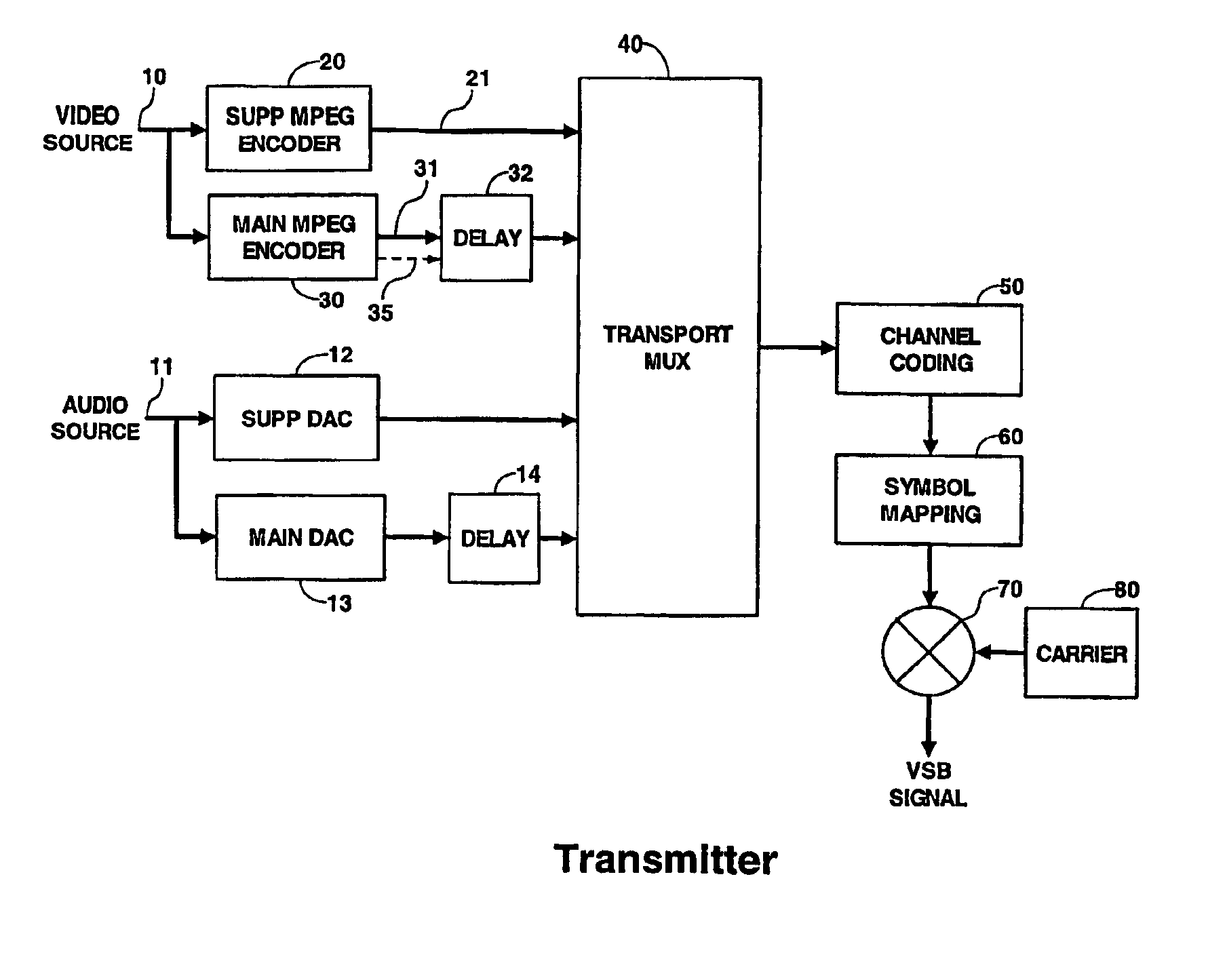
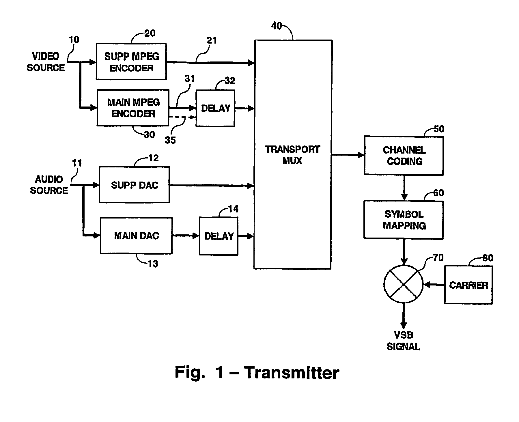
[0019]FIG. 1 is a block diagram of a transmitter incorporating the principles of the present invention. In the illustrated embodiment, the transmitter operates in accordance with the provisions of the Advanced Television Standards Committee (ATSC) digital television standard dated Sep. 16, 1995 which is incorporated herein by reference. However, one skilled in the art will understand that the principles of the present invention are applicable to any communications system in which the channel is subject to fading.

[0020]Video source material is applied via a terminal 10 to MPEG encoders 20 and 30. These encoders provide video signal encoding and compression in accordance with MPEG standards. The output from the encoder 20 is applied via conductor 21 to one input of a transport multiplexer 40. The encoder 30 processes the data stream in the same manner as encoder 20 but its output is applied via a conductor 31 to a packet buffer delay 32. The output of the delay 32 is applied to anothe...


PUM


Abstract

In a digital broadcast communications system, a higher priority component and a lower priority component are broadcast from a transmitter to a receiver. Each of these components generates a main and a supplemental signal, and each supplemental signal is advanced in time with respect to the corresponding main signal. The main and supplemental signals for both the higher and lower priority components are combined into a single signal, which is broadcast to a receiver. In the receiver, the time advanced supplemental signals are stored in a buffer to time align them with their corresponding main signals. Both main signals are processed in the normal manner in the receiver, and are also monitored to detect a fading event. When a fading event is detected, the corresponding buffered supplemental signals are substituted for the faded main signals and normal processing continues.

Description

[0001]This application claims the benefit under 35 U.S.C. §365 of International Application PCT / US02 / 23032 filed Jul. 19, 2002, which claims the benefit of U.S. Provisional Application No. 60 / 306,565, filed Jul. 19, 2001.BACKGROUND[0002]1. Field of the Invention[0003]The present invention relates to an improved transmission and reception system for digital television. More particularly the present invention is provided to overcome any fading of signal that may occur between the transmission and reception of a digital terrestrial TV system.[0004]2. Discussion of the Related Art[0005]Any terrestrial TV system must overcome a number of problems in transmitting signals to a receiver. For example, the United States has adopted the Advanced Television System Committee (ATSC) system using eight level vestigial side band (8-VSB) as its digital television standard. Because the VSB system is a single carrier modulation system, it is susceptible to fading caused by multipath transmission and s...

Claims


Application Information

Patent Timeline
IPC IPC(8): H04Q7/38H04L1/00H04L12/56H04B1/16H04N5/21H04N5/44H04N7/24H04N7/26H04N19/89H04W24/00H04W28/14H04W72/12
CPCH04H20/30H04N21/44209H04H20/72H04L1/007H04L1/0086H04L1/08H04N5/211H04N5/4401H04N21/2365H04N21/2383H04N21/4347H04N21/4382H04N19/37H04N19/39H04N19/89H04N19/67H04N21/234327H04N21/4392H04N21/44004H04H20/42H04L2001/0093H04N21/426H04N7/015
Inventor RAMASWAMY, KUMARKNUTSON, PAUL GOTHARDCOOPER, JEFFREY ALLEN
Owner MAGNOLIA LICENSING LLC
Why Eureka
Try Eureka