
Image-forming optical system

a technology of optical systems and optical paths, applied in the field of image-forming optical systems, can solve the problems of unfavorable cost increase, tightening of the accuracy required for each surface, and transferring surface accuracy errors and decentration accuracy errors while being added, etc., to achieve tightening of the tolerances required in the manufacturing process, reducing the cost of production, and improving space utilization efficiency

Inactive Publication Date: 2005-05-31
OLYMPUS CORP
View PDF11 Cites 57 Cited by
  • Summary
  • Abstract
  • Description
  • Claims
  • Application Information

AI Technical Summary

Benefits of technology

[0017]Accordingly, an object of the present invention is to provide a high-performance and low-cost image-forming optical system having a reduced number of constituent optical elements.
[0036]Further, a combination of two prisms allows construction of an image-forming optical system that is extremely thin as a whole. Further, because an image pickup device can be disposed at right angles to the viewing direction, it becomes easy to integrate the circuit board for driving the image pickup device into an apparatus incorporating the image-forming optical system. Accordingly, the apparatus can be constructed in a slim form.

Problems solved by technology

Accordingly, surface accuracy errors and decentration accuracy errors are transferred while being added up.
Consequently, the accuracy required for each surface becomes tight, causing the cost to increase unfavorably.
However, the optical system has an extremely narrow photographic field angle and is not satisfactorily corrected for aberrations.
In these examples, however, the zoom lens systems are not approximately telecentric on the image side and hence incapable of being applied to optical systems using image pickup devices such as CCDs.
Further, because the two prisms have a total of four reflecting surfaces, manufacturing tolerances are tightened, causing costs to increase unfavorably.
Further, if two reflecting surfaces are used in the prism positioned on the object side of the aperture stop, the height of extra-axial rays becomes high, causing the prism to become large in size undesirably.
However, these lens systems are not satisfactorily thin and compact.
All things considered, including the substrate of the image pickup device, it is difficult to form a very thin image pickup unit.
To correct the chromatic aberration and also correct other ray aberrations, the refracting optical system needs a large number of constituent elements, causing costs to increase.
In addition, because the optical path extends straight along the optical axis, the entire optical system undesirably lengthens in the direction of the optical axis, resulting in an unfavorably large-sized image pickup apparatus.
In decentered optical systems such as those described above in regard to the prior art, an imaged figure or the like is undesirably distorted and the correct shape cannot be reproduced unless the formed image is favorably corrected for aberrations, particularly rotationally asymmetric distortion.
Furthermore, in a case where a reflecting surface is used in a decentered optical system, the sensitivity to decentration errors of the reflecting surface is several times as high as that in the case of a refracting surface, and as the number of reflections increases, decentration errors that are transferred while being added up increase correspondingly.
Consequently, manufacturing accuracy and assembly accuracy, e.g. surface accuracy and decentration accuracy, required for reflecting surfaces become even more strict.

Method used


Image

  • Image-forming optical system
  • Image-forming optical system
  • Image-forming optical system

Examples


example 1

[0114]

SurfaceRadius ofSurfaceDisplacementRefractiveAbbe'sNo.curvatureseparationand tiltindexNo.Object∞∞plane1FFS[1]1.525455.82FFS[2] (RE)(1)1.525455.83FFS[3](2)4∞ (Stop)(3)5FFS[4](4)1.525455.86FFS[5] (RE)(5)1.525455.87FFS[6] (RE)(6)1.525455.88FFS[7](7)9∞(8)1.523055.010∞(9)Image∞(10)planeFFS[1]C4 −1.0876 × 10⁻²C6 1.8722 × 10⁻²C8 3.8132 × 10⁻³C10 −2.3015 × 10⁻³C11 −9.4351 × 10⁻⁴C13 7.1890 × 10⁻⁴C15 −2.0238 × 10⁻⁴C17 7.5766 × 10⁻⁷C19 6.5506 × 10⁻⁶C21 −2.2659 × 10⁻⁶FFS[2]C4 −3.4639 × 10⁻³C6 8.1383 × 10⁻³C8 −1.9758 × 10⁻⁴C10 2.9221 × 10⁻⁴C11 −5.5124 × 10⁻⁵C13 1.5479 × 10⁻⁴C15 6.6936 × 10⁻⁵C17 −8.5001 × 10⁻⁵C19 2.5214 × 10⁻⁵C21 5.5366 × 10⁻⁶FFS[3]C4 8.2999 × 10⁻³C6 −1.3417 × 10⁻²C8 −1.1302 × 10⁻²C10 3.6790 × 10⁻³C11 −6.3232 × 10⁻³C13 1.0246 × 10⁻³C15 −2.8677 × 10⁻³C17 −2.5809 × 10⁻⁵C19 7.5650 × 10⁻⁵C21 2.5953 × 10⁻⁵FFS[4]C4 −1.1382 × 10⁻²C6 8.5352 × 10⁻³C8 −3.7586 × 10⁻⁴C10 −2.4037 × 10⁻³C11 −6.7309 × 10⁻³C13 1.8517 × 10⁻⁴C15 −2.4090 × 10⁻³C17 3.3122 × 10⁻⁶C19 −3.6259 × 10⁻⁵C21 6.6768 × 1...

example 2

[0115]

SurfaceRadius ofSurfaceDisplacementRefractiveAbbe'sNo.curvatureseparationand tiltindexNo.Object∞∞plane1FFS[1]1.525455.82FFS[2] (RE)(1)1.525455.83∞(2)4∞ (Stop)(3)5∞(4)1.525455.86FFS[3] (RE)(5)1.525455.87FFS[4] (RE)(6)1.525455.88FFS[5](7)9∞(8)1.523055.010∞(9)Image∞(10)planeFFS[1]C4 −8.3188 × 10⁻³C6 3.4101 × 10⁻²C8 −1.4706 × 10⁻³C10 −1.1420 × 10⁻³C11 −6.5609 × 10⁻⁵C13 −1.7003 × 10⁻⁴C15 2.9132 × 10⁻⁴C17 9.7267 × 10⁻⁵C19 1.5357 × 10⁻⁵C21 −7.7116 × 10⁻⁶FFS[2]C4 −6.7737 × 10⁻⁴C6 9.5729 × 10⁻³C8 −4.6635 × 10⁻⁵C10 3.2706 × 10⁻⁴C11 4.7807 × 10⁻⁵C13 −1.7131 × 10⁻⁶C15 5.7208 × 10⁻⁵C17 1.8852 × 10⁻⁵C19 −1.0239 × 10⁻⁵C21 5.2505 × 10⁻⁶FFS[3]C4 1.8027 × 10⁻²C6 1.9843 × 10⁻²C8 2.7422 × 10⁻⁴C10 6.5409 × 10⁻⁴C11 −5.5779 × 10⁻⁵C13 7.9255 × 10⁻⁶C15 −1.3926 × 10⁻⁵C17 −1.0429 × 10⁻⁵C19 −2.8931 × 10⁻⁵C21 3.4435 × 10⁻⁷FFS[4]C4 1.5424 × 10⁻²C6 1.1204 × 10⁻²C8 −1.0357 × 10⁻⁴C10 3.0996 × 10⁻⁴C11 5.5084 × 10⁻⁵C13 4.6769 × 10⁻⁵C15 2.6581 × 10⁻⁵C17 1.3231 × 10⁻⁵C19 −3.7769 × 10⁻⁵C21 −2.3725 × 10⁻⁷FFS[5]C4 3...

example 3

[0116]

SurfaceRadius ofSurfaceDisplacementRefractiveAbbe'sNo.curvatureseparationand tiltindexNo.Object∞∞plane1FFS[1]1.525455.82FFS[2](1)3FFS[3](2)1.525455.84FFS[4] (RE)(3)1.525455.85FFS[5](4)6FFS[6](5)1.525455.87FFS[7](6)8∞ (Stop)(7)9FFS[8](8)1.525455.810FFS[9] (RE)(9)1.525455.811FFS[10](10)1.525455.8(RE)12FFS[11](11)Image∞(12)planeFFS[1]C4 2.0000 × 10⁻²C6 2.0000 × 10⁻²C4 1.1946 × 10⁻²C10 −5.8807 × 10⁻⁴C11 −7.9166 × 10⁻⁴C13 −7.1566 × 10⁻⁴C15 −1.0835 × 10⁻⁴FFS[2]C4 1.0000 × 10⁻¹C6 1.0000 × 10⁻¹C8 6.8147 × 10⁻³C10 4.9188 × 10⁻³C11 4.4453 × 10⁻⁴C13 1.4154 × 10⁻³C15 3.3510 × 10⁻⁴FFS[3]C4 1.7171 × 10⁻²C6 7.6775 × 10⁻²C8 3.1854 × 10⁻³C10 3.3543 × 10⁻³FFS[4]C4 −3.9048 × 10⁻³C6 1.0860 × 10⁻²C8 −1.3280 × 10⁻⁴C10 5.5067 × 10⁻⁴C11 −1.0727 × 10⁻⁴C13 −1.5579 × 10⁻⁴C15 1.2262 × 10⁻⁶C17 −2.4134 × 10⁻⁶C19 1.8572 × 10⁻⁶C21 1.4336 × 10⁻⁷FFS[5]C4 5.6286 × 10⁻³C6 −6.0994 × 10⁻³C8 −1.8177 × 10⁻²C10 6.0163 × 10⁻³FFS[6]C4 3.8725 × 10⁻²C6 5.1304 × 10⁻²C8 3.2587 × 10⁻³C10 −1.1068 × 10⁻³FFS[7]C4 −4.2787 × 10−...


PUM


Abstract

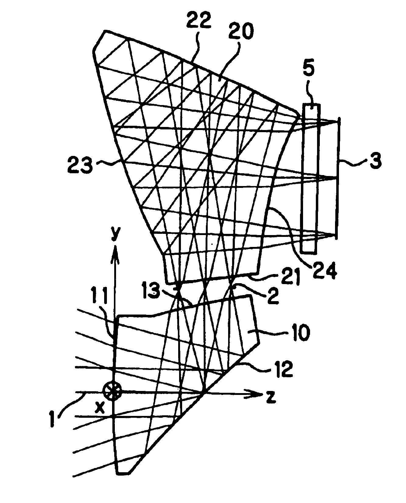
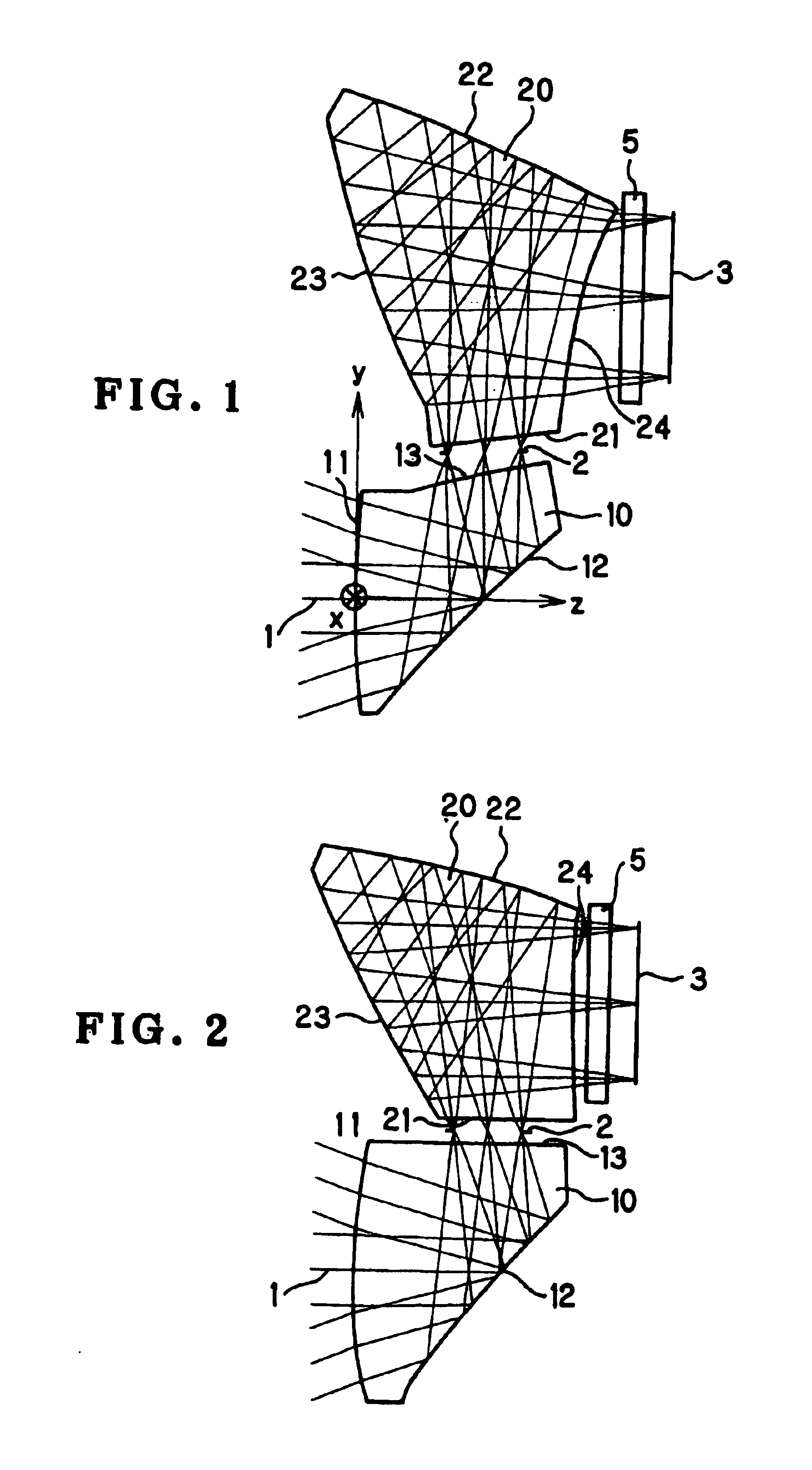
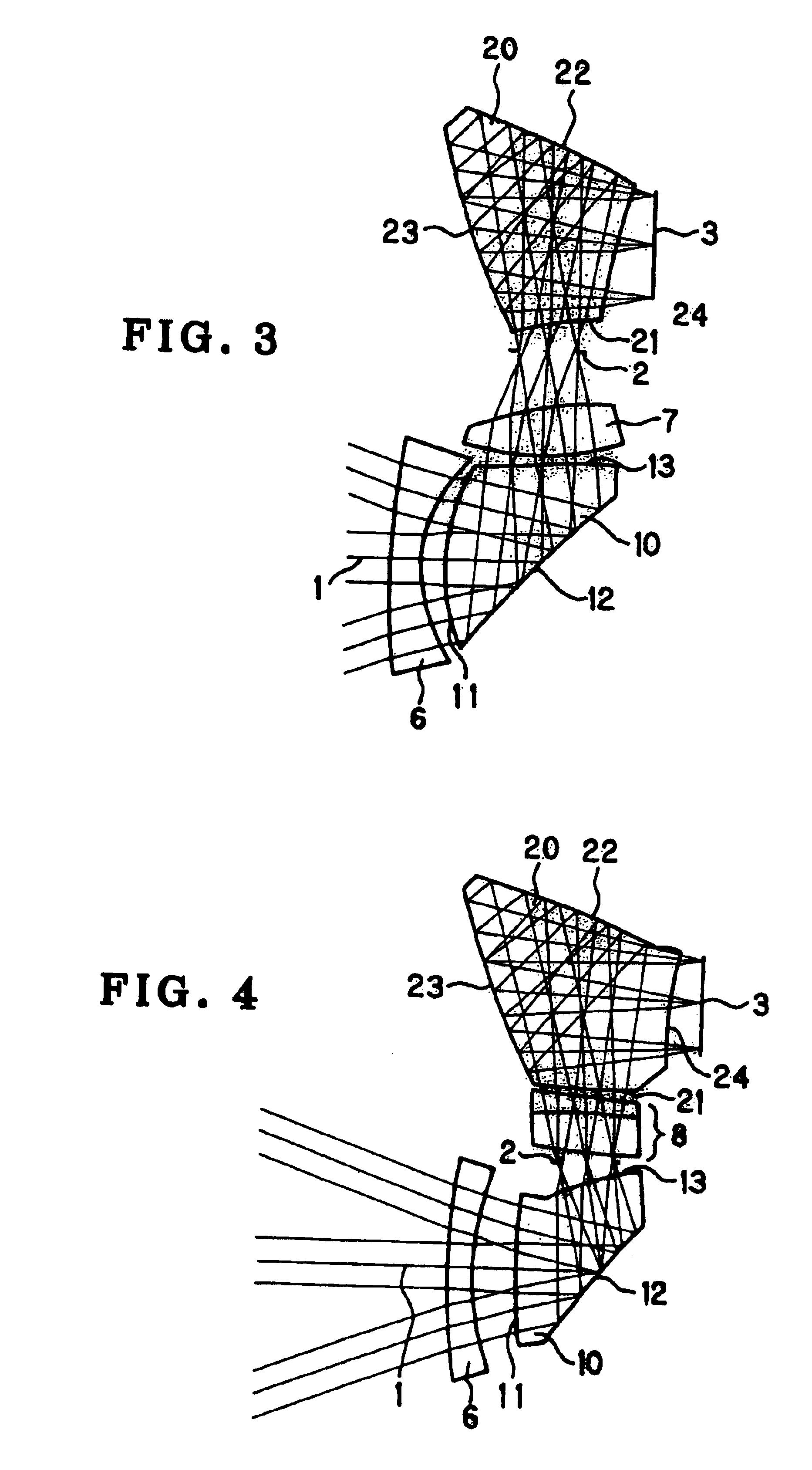
A high-performance and low-cost image-forming optical system has a reduced number of constituent optical elements and is made extremely thin, particularly in a direction perpendicular to an image pickup device, by folding an optical path using only three reflecting surfaces. The image-forming optical system has a front unit including a first prism 10, an aperture stop 2, and a rear unit including a second prism 20. The first prism 10 has a first transmitting surface 11, a first reflecting surface 12, and a second transmitting surface 13. The second prism 20 has a first transmitting surface 21, a first reflecting surface 22, a second reflecting surface 23, and a second transmitting surface 24. An optical path incident on the first reflecting surface 22 and an optical path exiting from the second reflecting surface 23 intersect each other. The first reflecting surface 12 of the first prism 10 and the first and second reflecting surfaces 22 and 23 of the second prism 20 have a curved surface configuration that gives a power to a light beam. The curved surface configuration is a rotationally asymmetric surface configuration that corrects aberrations due to decentration.

Description

[0001]This is a continuation of U.S. patent application Ser. No. 10 / 025,896, filed on Dec. 26, 2001, now U.S. Pat. No. 6,671,099 the contents of which are incorporated in their entirety herein by reference.[0002]This application claims benefit of Japanese Application No. 2000-392116 filed in Japan on Dec. 25, 2000, the contents of which are incorporated by this reference.BACKGROUND OF THE INVENTION[0003]1. Field of the Invention[0004]The present invention relates to image-forming optical systems. More particularly, the present invention relates to a decentered optical system with a reflecting surface having a power for use in optical apparatus using a small-sized image pickup device, e.g. video cameras, digital still cameras, film scanners, and endoscopes.[0005]2. Discussion of Related Art[0006]Recently, with the achievement of small-sized image pickup devices, image-forming optical systems for use in video cameras, digital still cameras, film scanners, endoscopes, etc. have also be...

Claims


Application Information

Patent Timeline
Patent Type & Authority Patents(United States)
IPC IPC(8): G02B17/08G02B13/00G03B13/06G02B5/04G02B13/18G02B23/26G02B25/00G03B17/02G03B17/17G03B19/02H04N5/225
CPCG02B13/0015G02B13/005G02B13/006G02B17/086G02B13/007G02B17/0832G02B17/0848G02B13/0065
Inventor NAGATA, TETSUO
Owner OLYMPUS CORP
Learn More