Optical fiber having a lower bending loss

a technology of optical fiber and bending loss, which is applied in the field of optical fibers having a lower bending loss, can solve the problems of increasing the transmission loss of optical fibers in optical fiber ribbons, the corners of stacked optical fiber ribbons showing the highest increase of transmission loss, and the conventional optical fiber is not suitable for wdm transmission around a wavelength of 1383 nm, etc., to suppress the increase of transmission loss and reduce the bending loss

Active Publication Date: 2005-05-31
FURUKAWA ELECTRIC CO LTD
View PDF5 Cites 51 Cited by
  • Summary
  • Abstract
  • Description
  • Claims
  • Application Information

AI Technical Summary

Benefits of technology

[0018]In order to overcome the above problem , it is an object of the present invention to provide an optical fiber having a lower bending loss and applicable for a slotted core optical f

Problems solved by technology

Thus, in general, the conventional optical fiber is not suitable for the WDM transmission around a wavelength of 1383 nm.
However, when bending is excessively applied to the optical fiber cable, the ends of the stacked optical fiber ribbons 20 may be pushed against the inner wall of the slot 32 and the transmission loss of the optical fibers in the optical fiber ribbons may increase, due to a lateral force therefrom.
Especially, four fibers at the corners of the stacked optical fiber ribbons tend to show higher increase of th

Method used


Image

  • Optical fiber having a lower bending loss
  • Optical fiber having a lower bending loss
  • Optical fiber having a lower bending loss

Examples


examples

[0048]Examples of the present embodiment will be described hereinafter.

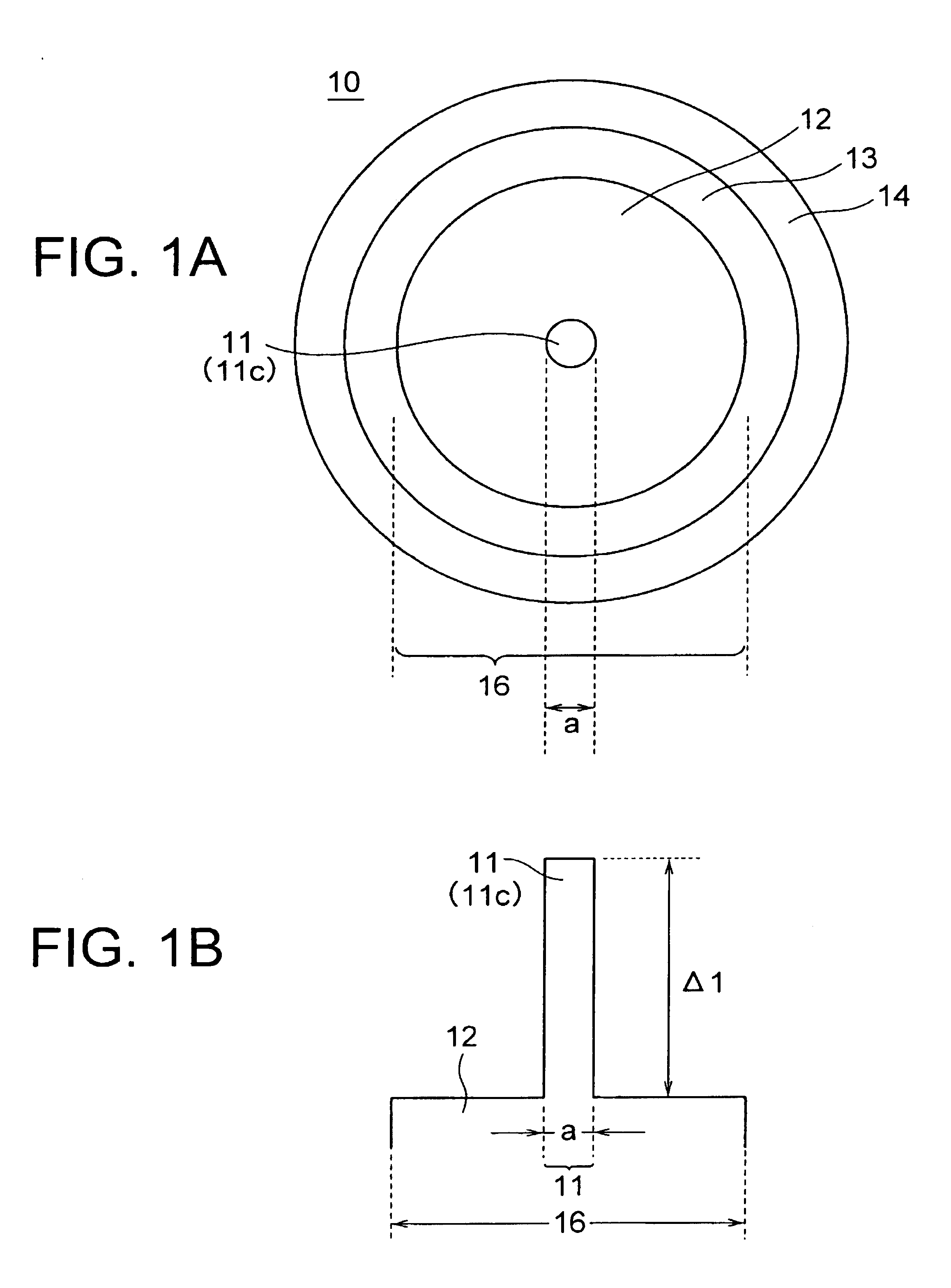
[0049]For fabricating the glass optical fiber 16 having the refractive index profile shown in the graph of FIG. 1B, an optical fiber preform was first manufactured. In the manufacturing of the optical fiber preform, a porous core soot including the first core and a part of the cladding was formed by using a vapour-phase axial deposition (VAD) method. The resultant porous preform was dehydrated and vitrified to obtain a core glass rod.

[0050]It should be noted here that, in order for suitable WDM transmission in a wavelength range of 1285 to 1625 nm, the absorption loss by the OH radical at a wavelength of 1383 nm should be reduced as much as possible, and the increase of the absorption loss even after exposure to hydrogen should be suppressed as much as possible. Therefore, it is required for the OH radicals not to mix into the optical fiber during a manufacturing process.

[0051]In view of the above, a technique is...


PUM

PropertyMeasurementUnit
Lengthaaaaaaaaaa
Fractionaaaaaaaaaa
Lengthaaaaaaaaaa

Abstract

An optical fiber includes a first core having a relative refractive index difference of larger than 0.36%, and a cladding. The optical fiber has fiber cut-off wavelength λc of more than 1350 nm, cable cut-off wavelength λcc of less than 1285 nm, bending loss at a wavelength of 1625 nm of not more than 10 dB/km when wound at a diameter of 20 mm, transmission loss at a wavelength range of 1285 to 1625 nm of not more than 0.40 dB/km, transmission loss at a wavelength of 1383 nm less than transmission loss at a wavelength of 1310 nm, and difference in transmission loss at a wavelength of 1383 nm of not more than 0.04 dB/km before and after exposure to hydrogen. The lower bending loss of the optical fiber provides an optical fiber cable for use in a WDM transmission in wavelength range of 1285 to 1625 nm.

Description

BACKGROUND OF THE INVENTION[0001](a) Field of the Invention[0002]The present invention relates to an optical fiber having a lower bending loss suitable for wavelength division multiplexing (WDM) transmission. The present invention also relates to an optical fiber cable including such an optical fiber.[0003](b) Description of the Related Art[0004]Along with the development of higher bit-rate and higher capacity optical transmission, the WDM transmission technique attracts larger attentions in the optical transmission field. In the current WDM transmission field, there are a request for further increasing the transmission capacity, and an attempt for enlarging the wavelength range for the optical transmission.[0005]It is noted in the conventional optical fiber that the optical fiber is likely to include as mixed impurities the OH group having an absorption peak around a wavelength of 1383 nm. Thus, in general, the conventional optical fiber is not suitable for the WDM transmission aro...

Claims


Application Information

Patent Timeline
IPC IPC(8): C03C13/04C03C25/60C03C13/00G02B6/036G02B6/02G02B6/44C03B37/018
CPCC03C13/047C03C25/607G02B6/02014G02B6/02223G02B6/03627G02B6/03633G02B6/02266G02B6/02395G02B6/4409
Inventor TAKAHASHI, FUMIOMORIDAIRA, HIDEYASHIBUTA, TAEKO
Owner FURUKAWA ELECTRIC CO LTD
Why Eureka
Try Eureka