Optical fiber and optical transmission system including the same

a technology applied in the field of optical fiber and optical transmission system, can solve the problems of difficult to make such an optical fiber having a very large relative refractive index difference, the absolute value of dispersion becomes so large, and achieves the effect of efficient transmission and efficient transmission

Inactive Publication Date: 2005-02-22
SUMITOMO ELECTRIC IND LTD
View PDF28 Cites 4 Cited by
  • Summary
  • Abstract
  • Description
  • Claims
  • Application Information

AI Technical Summary

Benefits of technology

In order to overcome problems such as those mentioned above, it is an object of the present invention to provide an optical fiber which enables efficient transmission c both of signal light in the 1.3-μm wavelength band and signal light in the 1.55-μm wavelength band, and an optical transmission system including the same.
The optical fiber according to the present invention is an optical fiber which enables efficient transmission of both of signal light in the 1.3-μm wavelength band and signal light in the 1.55-μm wavelength band, the optical fiber having only one zero-dispersion wavelength within a w

Problems solved by technology

The inventors have studied the prior art mentioned above and, as a result, found problems as follows.
Also, when signal light in the 1.552-μm wavelength band is transmitted through such a single-mode optical fiber, the absolute value of dispersion becomes so large that WDM communications cannot be carried out in a wide band.
However, it is dif

Method used


Image

  • Optical fiber and optical transmission system including the same
  • Optical fiber and optical transmission system including the same
  • Optical fiber and optical transmission system including the same

Examples


third embodiment

(Third Embodiment)

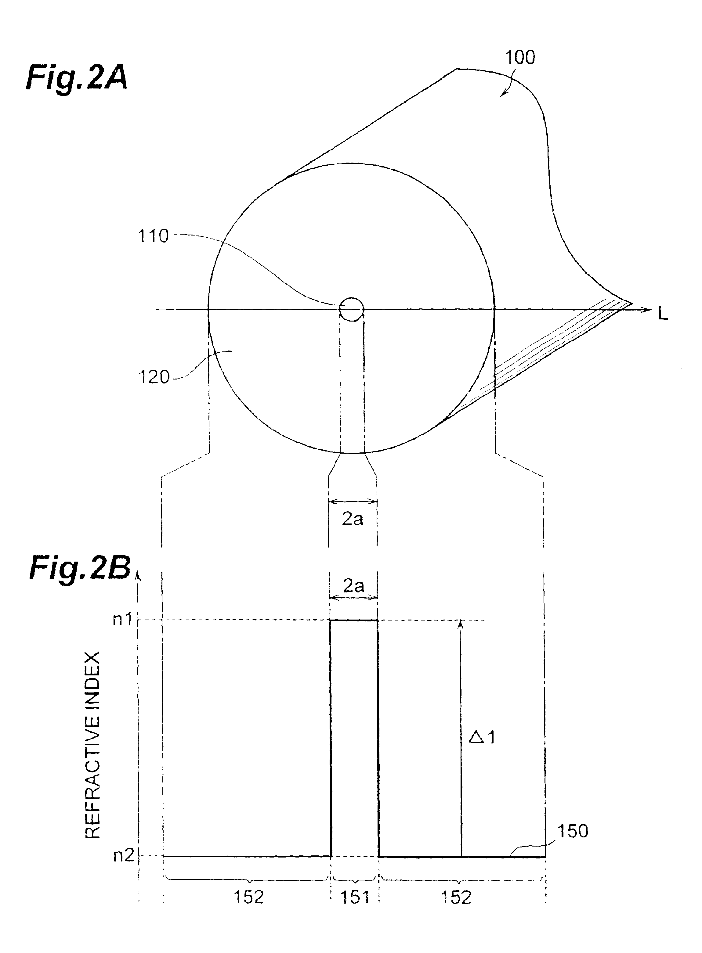
FIG. 4 is a refractive index profile of an optical fiber according to the third embodiment. The basic configuration of the optical fiber according to the third embodiment is also similar to that of the first embodiment shown in FIG. 2A, but is different therefrom in that the core region 110 shown in FIG. 2A is constituted by a first core and a second core. Referring to FIG. 2A for explaining the configuration of the optical fiber according to the third embodiment, the core region 110 comprises a first core, with an outside diameter 2a, having a maximum refractive index n1 at the optical axis center; and a second core with an outside diameter 2b, provided on the outer periphery of the first core, having are fractive index n2(<n1). The cladding region 120 provided on the outer periphery of the second core has a refractive index n1 (<n2).

As for the relationship between the refractive index profile 350 shown in FIG. 4 and the cross-sectional structure shown i...

fourth embodiment

(Fourth Embodiment)

FIG. 5 is a refractive index profile of an optical fiber according to the fourth embodiment. As in the first embodiment shown in FIG. 2A, the optical fiber according to the fourth embodiment comprises a core region 110 and a cladding region 120. However, it differs from the above-mentioned third embodiment in that the cladding region 120 comprises a depressed structure. Referring to FIG. 2A for explaining the configuration of the optical fiber according to the fourth embodiment, as in the third embodiment, the core region 110 comprises a first core, with an outside diameter 2a, having a maximum refractive index n1 at the optical axis center; and a second core with an outside diameter 2b, provided on the outer periphery of the first core, having a refractive index n2 (<n1). The cladding region 120 comprises an inner cladding with an outside diameter 2c, provided in contact with the outer periphery of the second core, having a refractive index n4 (<n2); an...

fifth embodiment

(Fifth Embodiment)

FIG. 6 is a refractive index profile of an optical fiber according to the fifth embodiment. The basic configuration of the optical fiber according to the fifth embodiment is also similar to the first embodiment shown in FIG. 2A, and is constituted by a core region 110 and a cladding region 120. As for the configuration of the optical fiber according to the fifth embodiment shown in FIG. 2A, the core region 110 comprises a first core, with an outside diameter 2a, extending along a predetermined axis and having a refractive index n1; a second core with an outside diameter 2b, provided on the outer periphery of the first core, having a refractive index n2 (<n1); and a third core with an outside diameter 2c, provided on the outer periphery of the second core, having a refractive index n3 (>n2, <n1). The cladding region 120 provided on the outer periphery of the third core 3 has a refractive index n4 (<n1, <n3).

As for the relationship between the ref...


PUM


Abstract

The present invention relates to an optical fiber which enables favorable optical communications in 1.3-μm and 1.55-μm wavelength bands, and an optical transmission system including the same. The optical fiber according to the present invention has only one zero-dispersion wavelength within a wavelength range of 1.20 μm to 1.60 μm, the zero-dispersion wavelength existing within a wavelength range of 1.37 μm to 1.50 μm , and has a positive dispersion slope at the zero-dispersion wavelength, thereby enabling favorable optical communications utilizing each signal light in the 1.3-μm and 1.55-μm wavelength bands sandwiching the zero-dispersion wavelength.

Description

BACKGROUND OF THE INVENTION1. Field of the InventionThe present invention relates to an optical fiber applicable to a transmission line in optical communications, and an optical transmission system including this optical fiber.2. Related Background ArtConventionally, as a transmission line in optical communications, standard single-mode optical fibers having a zero-dispersion wavelength in a 1.3-μm wavelength band (1280 nm to 1320 nm) have mainly been utilized. The transmission loss resulting from the main material (silica) of such an optical fiber has been known to become the lowest in a 1.55-μm wavelength band (1530 nm to 1565 nm). In addition, optical fiber amplifiers using an Er-doped optical fiber can amplify light in the 1.55-μm wavelength band at a high efficiency. For such a reason, disperson-shifted optical fibers designed so as to have a zero-dispersion wavelength in the 1.55-μm wavelength band are applied to transmission lines in wavelength division multiplexing (WDM) com...

Claims


Application Information

Patent Timeline
IPC IPC(8): G02B6/036G02B6/02H04B10/25H04B10/2507H04B10/2525H04B10/2543H04J14/00H04J14/02
CPCG02B6/02019G02B6/02223G02B6/02242G02B6/02271G02B6/03666G02B6/03627G02B6/03633G02B6/03644G02B6/0365G02B6/03611G02B6/0281G02B6/036G02B6/00
Inventor KATO, TAKATOSHISASAOKA, EISUKETANAKA, SHIGERU
Owner SUMITOMO ELECTRIC IND LTD
Why Eureka
Try Eureka