
System for spacing flutes on a workpiece

a technology of workpieces and flutes, which is applied in the direction of tongue/groove making apparatus, manufacturing tools, instruments, etc., can solve the problems of incomplete workpieces, unusable entire workpieces for the desired application, and complicated preparation of workpieces to be routed. , to achieve the effect of minimizing setup time, minimizing setup time, and minimizing setup tim

Inactive Publication Date: 2005-06-07
LOCAPUTO DANIEL R
View PDF30 Cites 19 Cited by
  • Summary
  • Abstract
  • Description
  • Claims
  • Application Information

AI Technical Summary

Benefits of technology

[0007]It is an object of the invention to minimize the setup time required to route one flute in a workpiece. It is another object of the invention to minimize the setup time required to route more than one equally-spaced and positioned flutes in a workpiece. It is another object of the invention to minimize the setup time required to route one stop-flute in a workpiece. It is another object of the invention to minimize the set up time required to route more than one equally-spaced and positioned stop-flutes in a workpiece. It is another object of the invention to create more than one flute without changing the fence relative to the router bit. It is another object of the invention to adjust the fence relative to the router bit and route two flutes in a workpiece without readjusting the fence.SUMMARY OF THE INVENTION
[0008]The present invention provides a system, apparatus, and method for achieving these objects. More particularly, the system of the present invention utilizes a router table with an attached router and router bit, a router fence slidably attached to the router table, and a flute-spacing jig. The flute-spacing jig apparatus of the present invention includes a plurality of spaced alignment holes, a fence guide, and a workpiece aligner whereby a workpiece may be desirably positioned for routing spaced flutes. The present invention also provides for a T-square slidably attached to the router table, which has adjustable, removable or hinged stop-blocks attached to it, thereby facilitating the routing of evenly-spaced stop-flutes in a workpiece.

Problems solved by technology

While the routing of a flute in a workpiece can be a fairly straightforward process, the measuring and aligning of the workpiece to create equally-spaced multiple flutes can be a very time-consuming and tedious process.
The preparation of a workpiece to be routed is further complicated when stop-flutes are desired to be routed in the workpiece.
In some cases, errors in measurement, or errors in alignment and routing, can cause the entire workpiece to become unusable for the desired application, and it must be discarded.

Method used


Image

  • System for spacing flutes on a workpiece
  • System for spacing flutes on a workpiece
  • System for spacing flutes on a workpiece

Examples


Embodiment Construction

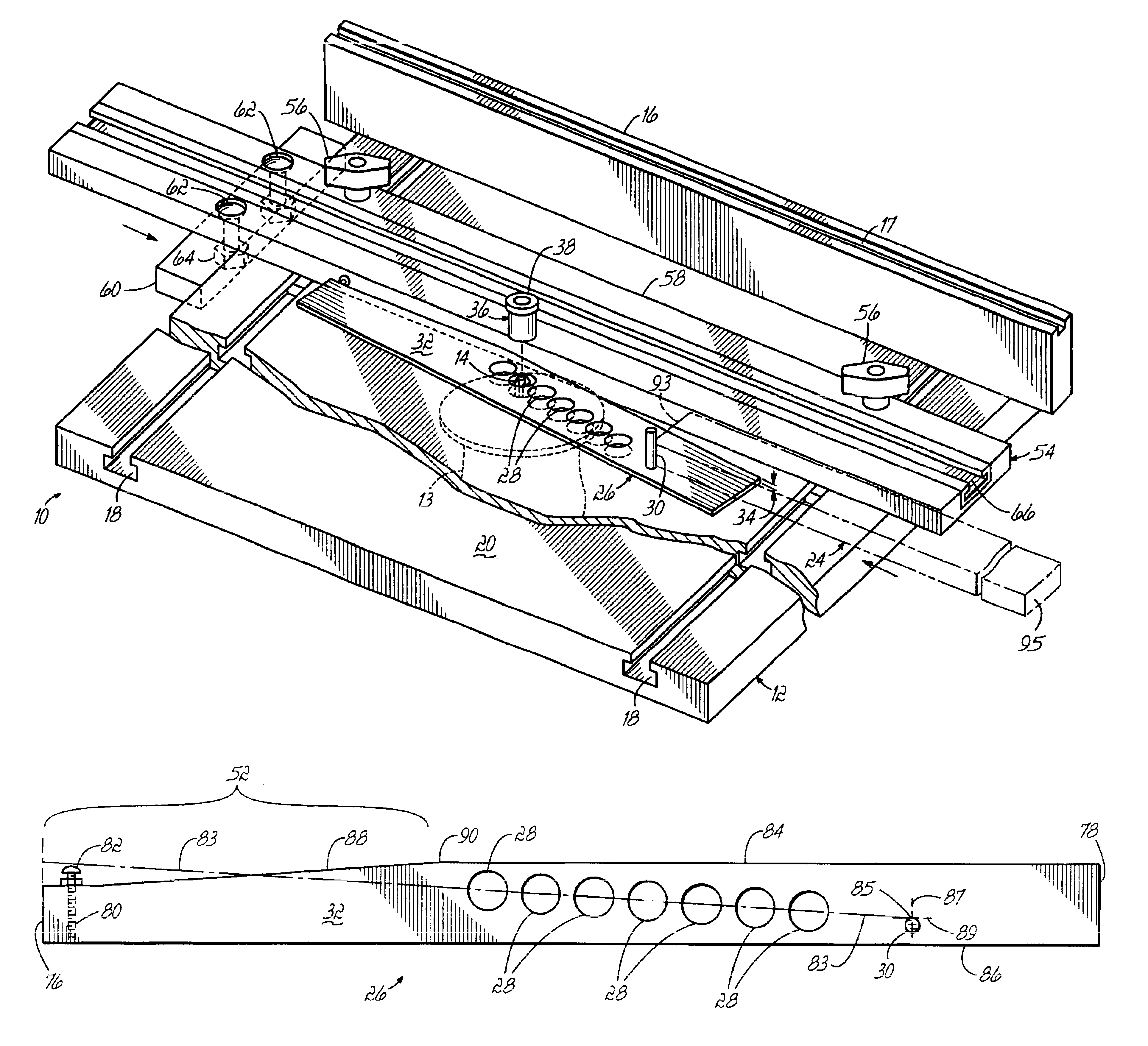
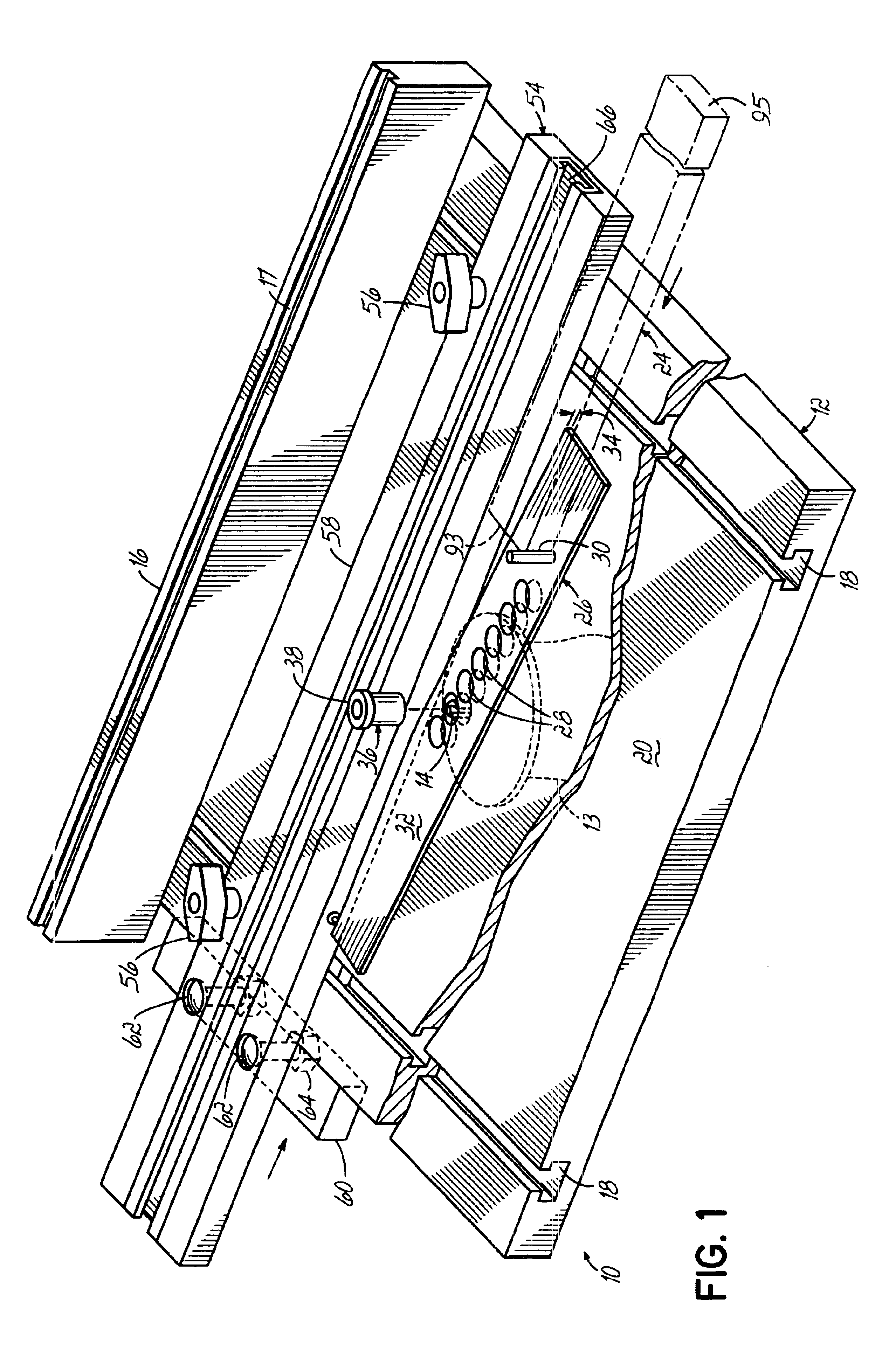
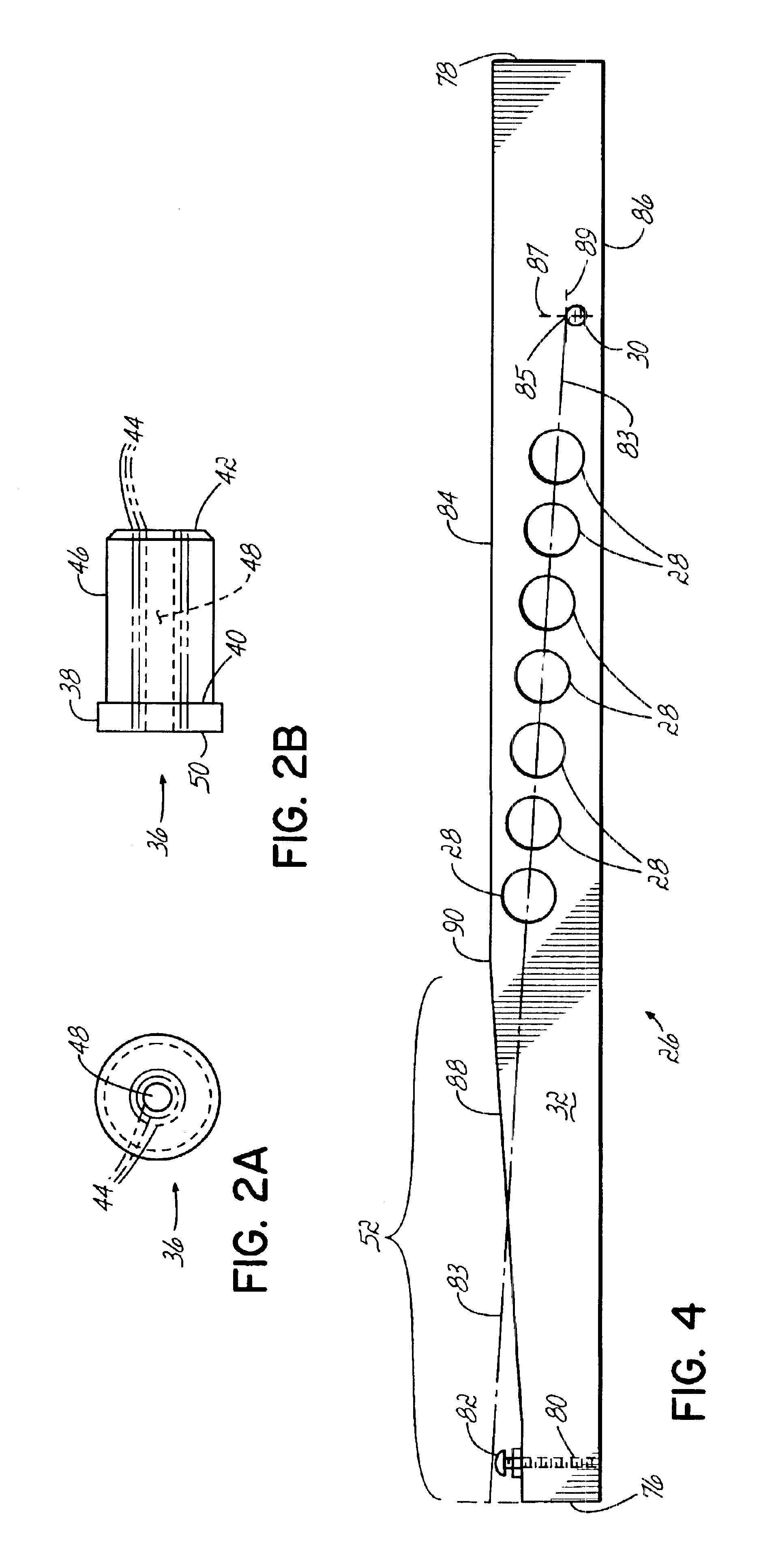
[0032]Referring to the figures and to FIG. 1 in particular, the system 10 of the present invention for spacing flutes in a workpiece is comprised of a router table 12, which has attached to it a router 13 and a router bit 14. Additionally, the router table 12 has a router fence 16, which is slidably attached to the router table 12 via channels or tracks 18. The router fence 16 can thus be moved toward and away from the router bit 14, as desired. A longitudinal channel 17 is also positioned in the router fence 16. The router bit 14 typically extends above the top surface 20 of the router table 12 at a distance corresponding to the desired depth of the muted flute 22 in a workpiece 24. As shown, the system 10 also comprises a flute-spacing jig 26, which has a plurality of generally spaced alignment holes 28. Another embodiment of the flute-spacing jig 26 could have only one alignment hole 28. Such a flute-spacing jig 26 could be used to route one or two flutes 22 in a workpiece 24. Th...


PUM


Abstract

A system, apparatus, and method for spacing and aligning flutes to be routed in a workpiece is disclosed. The system includes a flute-spacing jig with spaced alignment holes, a workpiece aligner, and a fence guide. Additionally, the system can include a T-square with adjustable stop-blocks.

Description

FIELD OF THE INVENTION[0001]The present invention relates to woodworking tools in general and, more particularly, to woodworking involving the routing of flutes in a workpiece.BACKGROUND OF THE INVENTION[0002]The cutting, or routing, of flutes in a workpiece, such as a board, has been done for many years. Typically in a woodworking context, flutes are routed in a board using a router table, which is well known in the industry. A typical router table has a router attached to the underside of the table whereby a router bit protrudes upward through an opening in the table surface. Boards or other workpieces are then moved across the router table and over the rotating router bit, whereby a flute is cut or routed in the board.[0003]A typical router table also has a router fence attached to it, which can be used to guide a workpiece as it is being slid across the router table. Typically, the router fence is slidably adjusted on the router table to accommodate different width workpieces or...

Claims


Application Information

Patent Timeline
IPC IPC(8): G01D21/00B23Q3/00B27C5/06B27F1/02
CPCB23Q3/005B27F1/02B27C5/06
Inventor LOCAPUTO, DANIEL R.
Owner LOCAPUTO DANIEL R
Learn More