Method and apparatus for lathe tool alignment

a technology of lathe tool alignment and method, which is applied in the field of machine tools, can solve the problems of requiring a considerable amount of setup time, involving significant and costly setup time, and special tooling, and achieves the effect of reducing the setup time required

Active Publication Date: 2013-02-14
FREILICH DANIEL S
View PDF9 Cites 0 Cited by
  • Summary
  • Abstract
  • Description
  • Claims
  • Application Information

AI Technical Summary

Benefits of technology

[0006]The present invention is directed to a method and apparatus for orienting and rigidly clamping a cutting tool in alignment with a lathe's spindle axis in a manner to minimize the setup time required. More particularly, the present invention is directed to a method and apparatus which uses the lathe's workpiece holding mechanism (hereinafter generally referred to as a “spindle chuck”) for establishing the angular orientation and radial position of a cutting tool retainer in order to locate the cutting tool for cutting in alignment with the lathe's spindle axis.

Problems solved by technology

Various techniques have been employed to achieve precision alignment, often involving significant and costly setup time and special tooling.
This careful positioning and orienting of the cutting tool typically requires a considerable amount of setup time by a person skilled in such procedures.

Method used


Image

  • Method and apparatus for lathe tool alignment
  • Method and apparatus for lathe tool alignment
  • Method and apparatus for lathe tool alignment

Examples


first embodiment

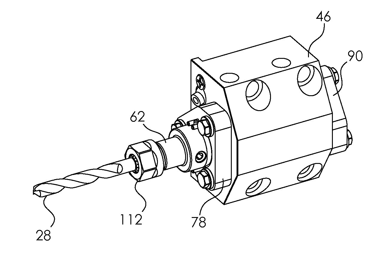
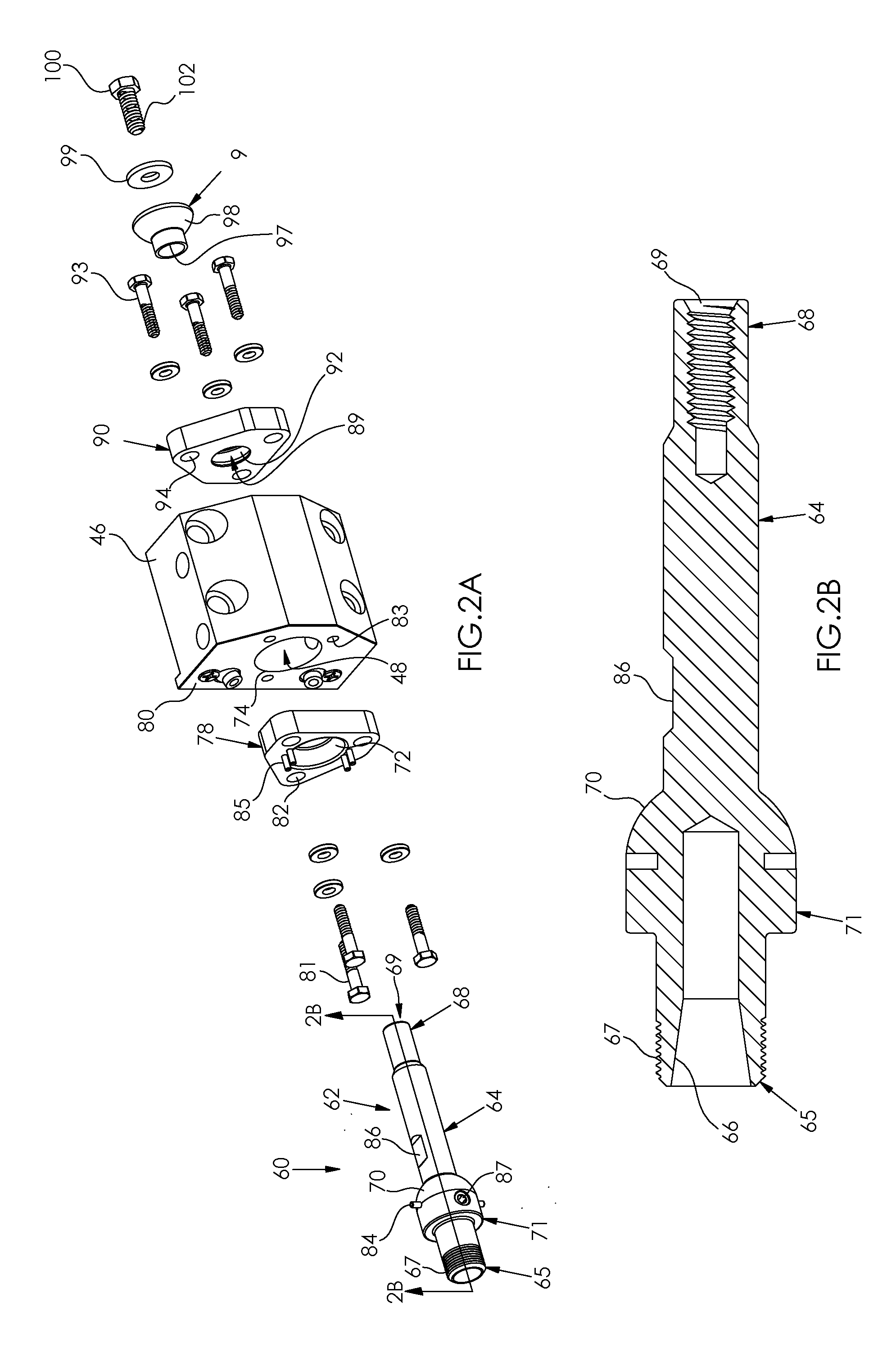
[0043]Attention is now directed to FIGS. 2A, 2B, 3A, 3B, and 4 which illustrate a preferred apparatus in accordance with the invention configured for use in conjunction with the exemplary tool block 46 of FIG. 1. The apparatus includes a tool retainer 60 comprising a specially configured collet chuck 62. The collet chuck 62 comprises an elongate body 64 having a front end 65 defining a tapered internal pocket 66 and having external threads 67. The collet chuck rear end 68 has an internally threaded axial recess 69. The body 64 carries a convex spherical positioning surface 70 on a protuberance, or positioning member, 71 located between said body front end 65 and rear end 68.

[0044]The collet chuck body 64 is dimensioned to extend through the tool block bore 48 with the spherical positioning surface 70 adapted to engage a concave spherical receiving surface 72 located proximate to the entrance 74 of the bore 48. When using a standard tool block 46, the concave spherical receiving surf...

second embodiment

[0056]From the foregoing, it should now be understood that a preferred method and apparatus have been described which directly utilize a lathe's spindle chuck to orient a tool retainer for aligning a cutting tool with the lathe's spindle axis. It is recognized that several variations and modifications can be made to better satisfy particular situations. For example, certain users may prefer to avoid having to machine holes 83 and 95 into their existing tool block 46. To satisfy this situation, the invention is illustrated in FIGS. 6 and 7.

[0057]FIG. 6 is similar to FIG. 2A but avoids bolting socket members 78 and 90 directly the tool block 46. Instead, a receiver member 150 is provided comprised of a tubular portion 152 dimensioned to fit closely into tool block bore 48 and a front flange member 154 attached to the front end 156 of tubular portion 152. The rear end 158 of the tubular portion is internally threaded for receiving the externally threaded nipple 160 of rear flange membe...

third embodiment

[0058]Attention is now directed to FIGS. 8, 9A, 9B, 9C, and 10 which depict the invention characterized by the use of a mandrel for aligning the collet chuck with the lathe's spindle axis. More particularly, some users may prefer to avoid directly clamping the spindle chuck jaws 21 against the external threads 67 of the collet chuck front end as is represented in FIGS. 5A-5F. Accordingly, in the embodiment of FIG. 8, an elongate mandrel 200 is provided comprising a body 202 having a front end 204 and a rear end 206. The front end 204 is preferably cylindrically shaped and adapted to be readily grasped by the spindle chuck jaws 21 (FIG. 9A). The rear end 206 is tapered at 208 in a manner to nest closely in a tapered internal pocket 210 at the front end 212 of collet chuck 214. An external thread 216, preferably left handed, is provided on the mandrel body 202 adapted to be threaded into nut 218. The external thread 220 on collet chuck front end 212 is also adapted to be threaded into...


PUM

PropertyMeasurementUnit
radial movementaaaaaaaaaa
rotational movementaaaaaaaaaa
areaaaaaaaaaaa

Abstract

A method and apparatus for orienting and rigidly clamping a cutting tool in alignment with a lathe's spindle axis in a manner to minimize the setup time required. The method and apparatus uses the lathe's spindle chuck for establishing and clamping the angular orientation and radial position of a cutting tool retainer in order to align the cutting tool with the lathe's spindle axis.

Description

RELATED APPLICATIONS[0001]This application claims the benefit of U.S. Provisional Application 61 / 574,775 filed Aug. 9, 2011.FIELD OF THE INVENTION[0002]This invention relates generally to machine tools and more particularly to a method and apparatus for aligning a cutting tool, e.g., a drill bit, with the spindle axis of a rotating workpiece machine, i.e., a lathe.BACKGROUND[0003]Various types of lathes are well known in the art for cutting metal and other materials. They are generally characterized by a headstock including a spindle chuck for holding a workpiece and a drive mechanism for rotating the workpiece with respect to a spindle axis. A typical lathe further includes a carriage supporting a tool holding mechanism for selective axial movement parallel to the spindle axis and lateral movement perpendicular to the spindle axis. Modern CNC lathes generally also include a tool changer mechanism comprised of multiple tool holders, where each tool holder is capable of mounting a si...

Claims


Application Information

Patent Timeline
Patent Type & Authority Applications(United States)
IPC IPC(8): B23B29/00B23B1/00
CPCB23B29/205B23B25/06Y10T82/2574Y10T29/49826Y10T82/2579
Inventor FREILICH, DANIEL S.
Owner FREILICH DANIEL S
Why Eureka
Try Eureka