

Pultruded fiberglass reinforced plastic underground vault construction
- Summary
- Abstract
- Description
- Claims
- Application Information
AI Technical Summary
Benefits of technology
Problems solved by technology
Method used
Image

Examples
Embodiment Construction
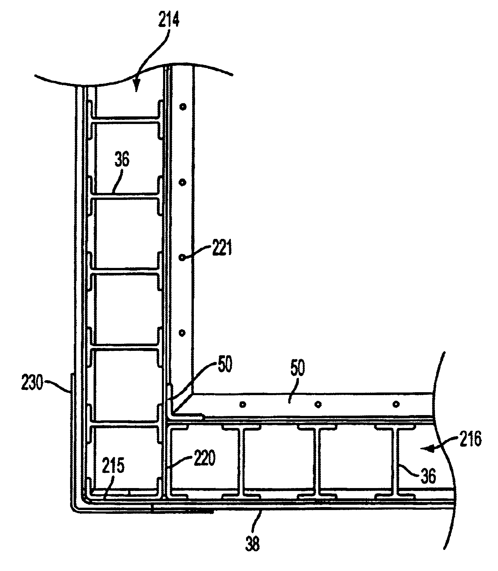
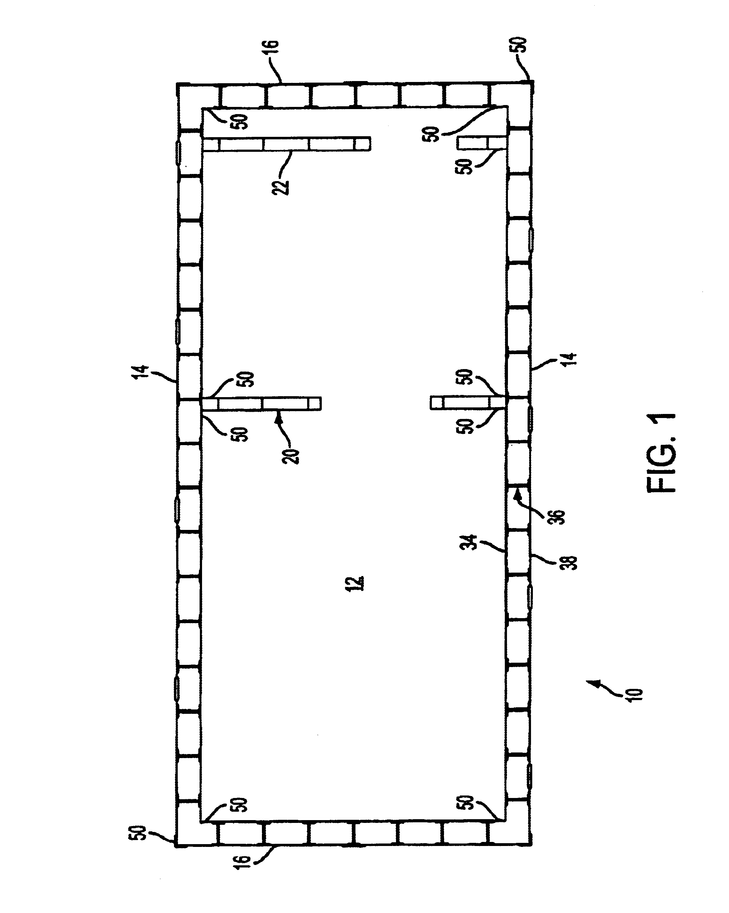
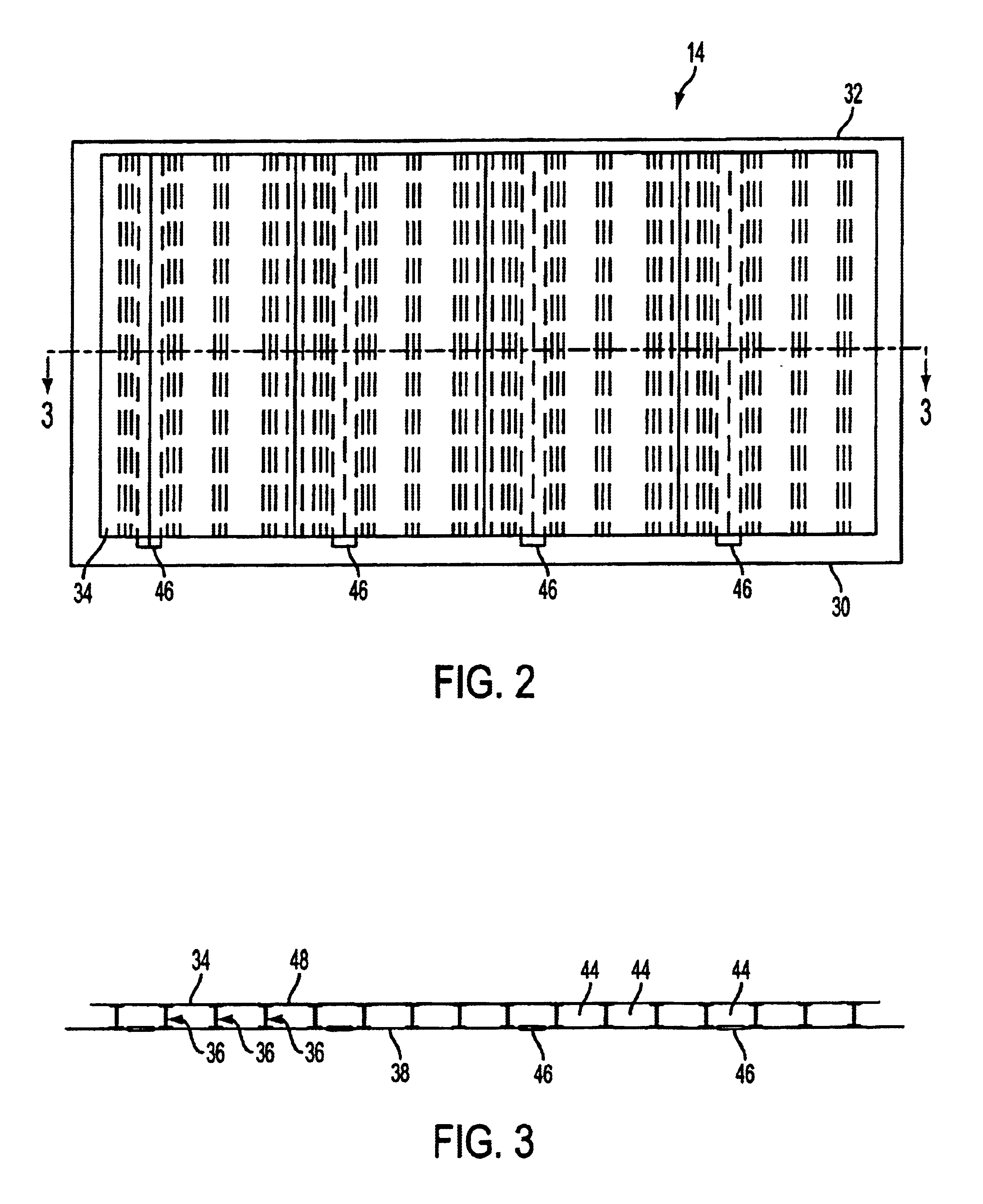
[0041]Referring to FIGS. 1-29, an enclosure structure of fiber reinforced plastic, in accordance with the present invention is illustrated. The enclosure structure is preferably used in a buried or subterranean environment wherein earth material, such as dirt, sand, and rocks, substantially covers the entire structure. The enclosure structure is herein referred to as a vault, and designated as reference numeral 10 (in FIGS. 1-13) and numeral 200 (in FIGS. 14-29).
[0042]As used herein throughout the specification, reference to a pultruded component designates the component is created by a process of pultrusion. Pultrusion is a method of manufacturing reinforced plastic shapes that includes continuously pulling resin rich reinforcements through a heated steel die to form profiles of constant cross section of continuous length. Pultrusion has not been used for constructing for vault components and panels as described in the exemplary embodiments of the present invention.
[0043]Referring ...
PUM
| Property | Measurement | Unit |
|---|---|---|
| Fraction | aaaaa | aaaaa |
| Weight | aaaaa | aaaaa |
| Stiffness | aaaaa | aaaaa |
Abstract
Description
Claims
Application Information