Fueling system vapor recovery and containment leak detection system and method

a technology of leak detection system and fueling system, which is applied in the direction of fluid tightness measurement, instruments, packaged goods, etc., can solve the problems of leakage at a dispensing point coupled to the afs, leakage at one or more dispensing points,

Inactive Publication Date: 2005-06-07
VEEDER ROOT
View PDF120 Cites 23 Cited by
  • Summary
  • Abstract
  • Description
  • Claims
  • Application Information

AI Technical Summary

Benefits of technology

[0014]In one embodiment of the present invention, the AFS is placed in each vapor return passage coupled to one or more dispensing points in a fuel dispenser. In this manner, the AFS registers vapor flow recovered by each individual dispensing point. If the AFS registers vapor flow when such one or more dispensing points are idle, a leak is present at a dispensing point coupled to the AFS. If the vapor or air flow detected by the AFS is “forward vapor flow,” this is indicative of outside air being ingressed into the leak point of the dispensing point. If the vapor flow detected by the AFS is “reverse vapor flow,” this is indicative of vapor from the storage tank being egressed out of the leak point of the dispensing point.
[0015]In a second embodiment of the present invention, an AFS is placed in the common vapor return pipe that is coupled to one or more vapor return passages of the individual dispensing points. In this manner, the AFS registers vapor flow for each of the vapor return passages coupled to the

Problems solved by technology

The leak may be due to a defective air-valve in the nozzle, or a loose or defective fitting or coupling at the nozzle or in the hose and fuel conduit coupled to the nozzle, that does not properly close when the dispensing point is idle, or the leak may be due to a leak in the hose connected to the nozzle or anywhere in the vap

Method used


Image

  • Fueling system vapor recovery and containment leak detection system and method
  • Fueling system vapor recovery and containment leak detection system and method
  • Fueling system vapor recovery and containment leak detection system and method

Examples


Embodiment Construction

[0024]This application is a continuation-in-part application of U.S. patent application Ser. No. 09 / 725,727, filed on Nov. 30, 2000 and incorporated herein by reference in its entirety, which is an application that relates to and claims priority to (1) U.S. Provisional Patent Application Ser. No. 60 / 168,029, filed on Nov. 30, 1999 entitled “Fueling System Vapor Recovery Performance Monitor” incorporated herein by reference in its entirety; (2) U.S. Provisional Patent Application Ser. No. 60 / 202,054, filed on May 5, 2000, entitled “Fueling System Vapor Recovery Performance Monitor” incorporated herein by reference in its entirety; and (3) U.S. Provisional Patent Application Ser. No. 60 / 202,659, filed on May 8, 2000, entitled “Method of Determining Failure of Fuel Vapor Recovery System” incorporated herein by reference in its entirety.

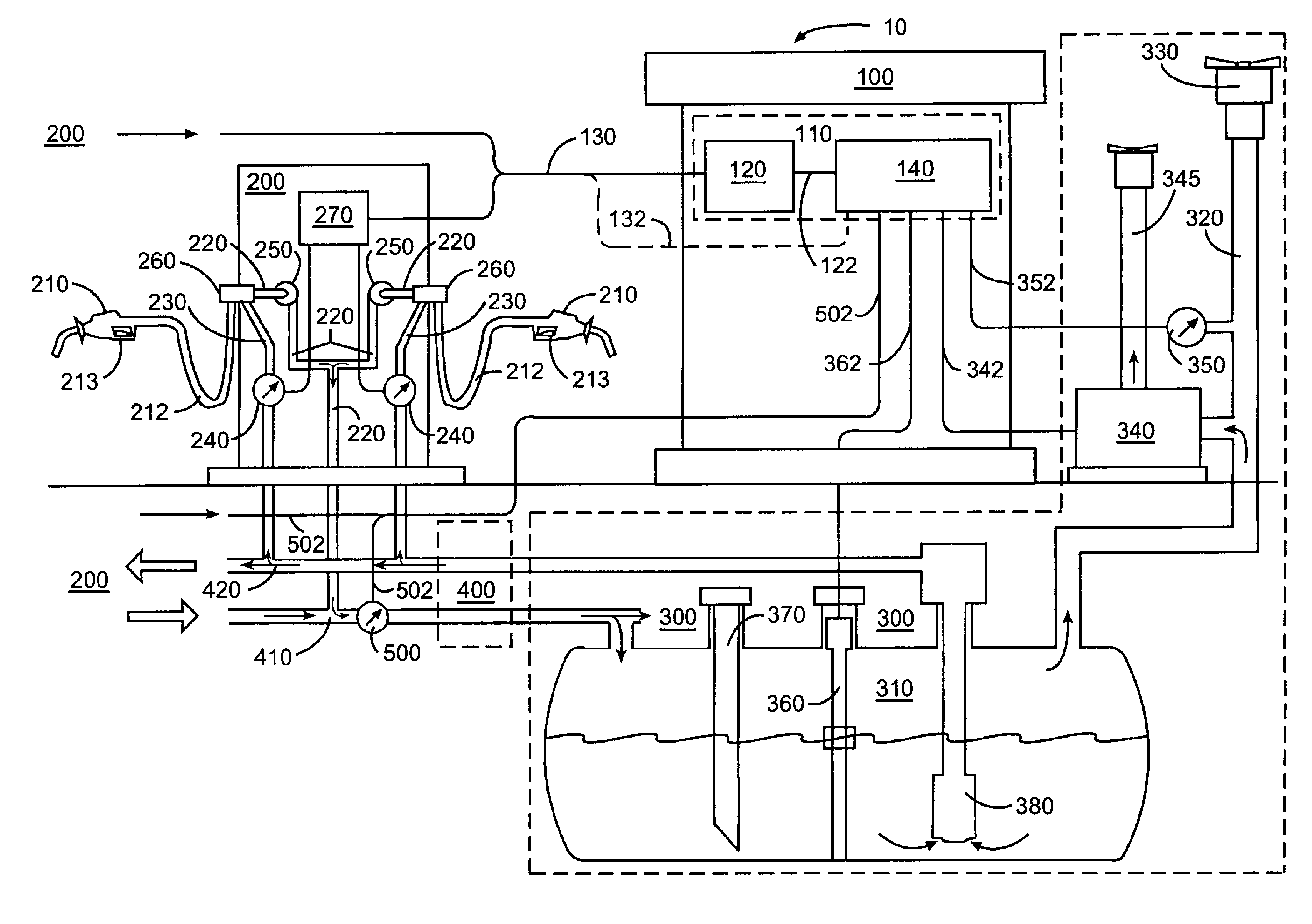
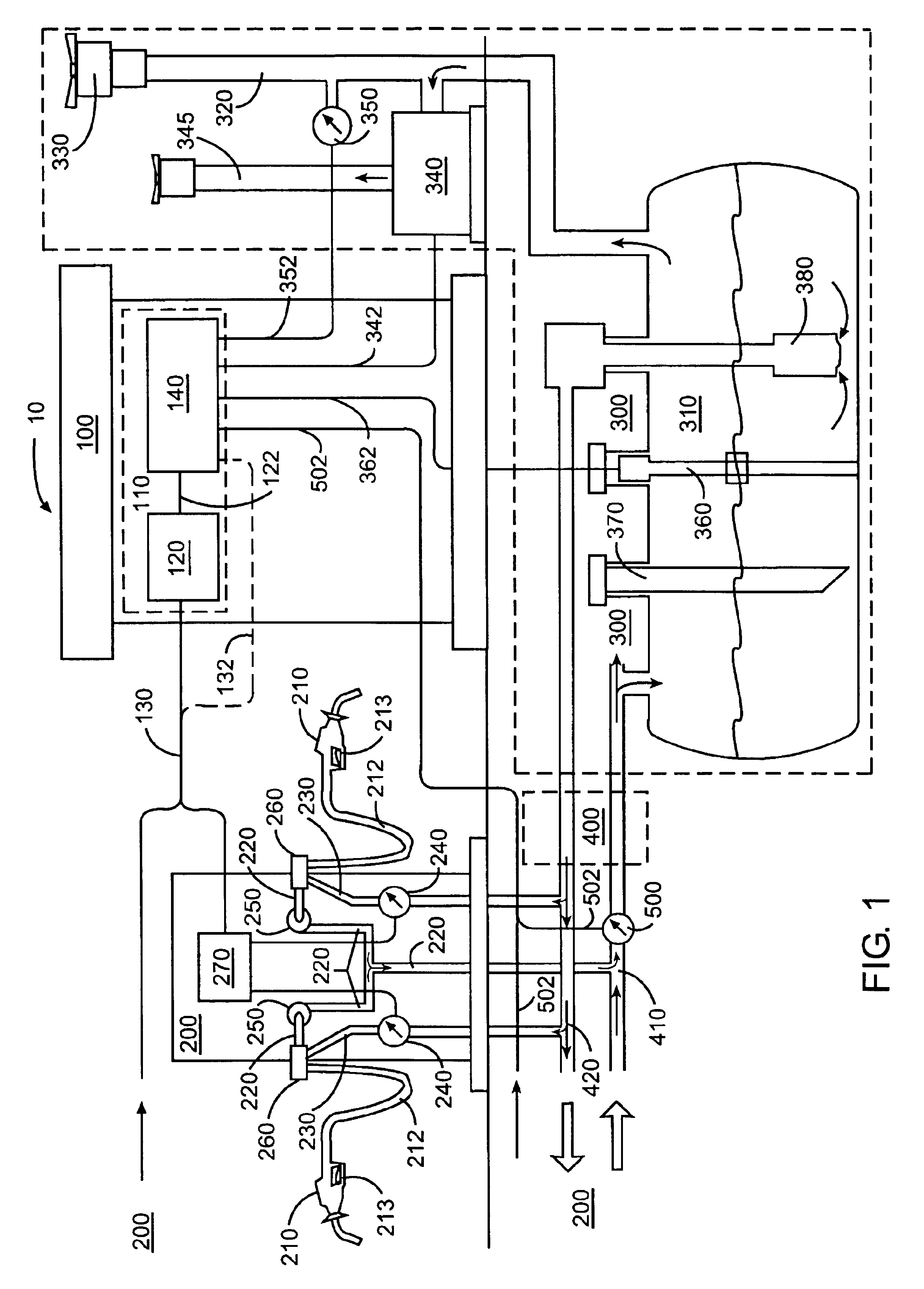
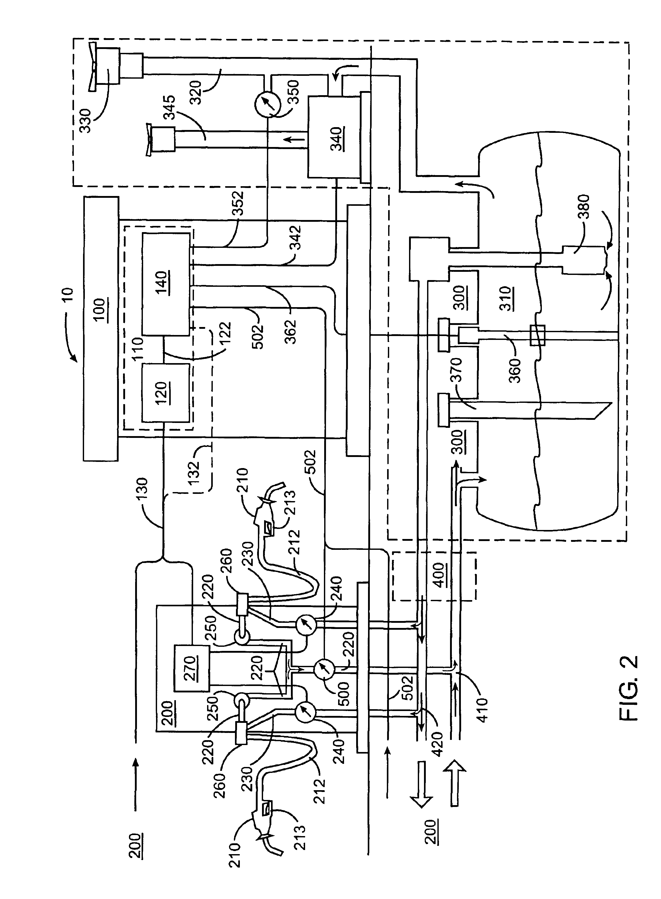
[0025]The present invention relates to detection of a leak at a dispensing point in in a fuel dispenser vapor recovery system. An air-flow sensor (AFS),...


PUM

PropertyMeasurementUnit
Flow rateaaaaaaaaaa

Abstract

A method and apparatus for monitoring a fuel vapor recovery system to determine if a leak condition exists in either the vapor return passage in a fuel dispenser or a common vapor return pipe. An air-flow sensor (AFS) may be located in the common vapor return pipe for all of the dispensing points at a service station, or in each fuel dispenser and coupled to the dispensing points of the fuel dispenser. The AFS registers vapor flow recovered by a dispensing point(s) that is returned back to the storage tank. If the AFS measures vapor flow when such dispensing point(s) coupled to such AFS is not actively recovering vapor, this is indicative of a leak in such dispensing point(s). The leak condition is reported by a tank monitor or other reporting system so that appropriate measures can be taken.

Description

CROSS REFERENCE TO RELATED APPLICATIONS[0001]This application is a continuation-in-part application of U.S. patent application Ser. No. 09 / 725,727, filed on Nov. 30, 2000 now U.S. Pat. No. 6,622,751, which is an application that relates to and claims priority to (1) U.S. Provisional Patent Application Ser. No. 60 / 168,029, filed on Nov. 30, 1999, entitled “Fueling System Vapor Recovery Performance Monitor;” (2) U.S. Provisional Patent Application Ser. No. 60 / 202,054, filed on May 5, 2000, entitled “Fueling System Vapor Recovery Performance Monitor;” and (3) U.S. Provisional Patent Application Ser. No. 60 / 202,659, filed on May 8, 2000, entitled “Method of Determining Failure of Fuel Vapor Recovery System.”FIELD OF THE INVENTION[0002]The present invention relates to a fueling system vapor recovery and containment leak detection system.BACKGROUND OF THE INVENTION[0003]Gasoline dispensing facilities (i.e. gasoline stations) often suffer from a loss of fuel to the atmosphere due to inadeq...

Claims


Application Information

Patent Timeline
IPC IPC(8): B67D5/01B67D5/04B67D7/04
CPCB67D7/0496B67D7/0486
Inventor HART, ROBERT P.
Owner VEEDER ROOT
Why Eureka
Try Eureka