
Method and apparatus for bonding a flexible printed circuit cable to an ink jet print head assembly

a flexible printed circuit and ink jet technology, applied in printed circuit manufacturing, printed circuit aspects, printing, etc., can solve the problems affecting the integrity of the print head die and any other parts of the ink, and leaving a considerable length of the fpc cable. , to achieve the effect of reducing the time spent on bonding a conductor

Inactive Publication Date: 2005-06-07
S PRINTING SOLUTION CO LTD
View PDF10 Cites 6 Cited by
  • Summary
  • Abstract
  • Description
  • Claims
  • Application Information

AI Technical Summary

Benefits of technology

[0011]To solve the above-described problems, it is an aspect of the present invention to provide an ink jet print head assembly and a method and apparatus for bonding a flexible printed circuit (FPC) cable to an ink jet print head assembly, in which the time spent to bond a conductor is decreased.
[0012]In accordance with another aspect of the present invention, there is provided an ink jet print head assembly and a method and apparatus for bonding an FPC cable to an ink jet print head assembly, in which the portion where a conductor and a pad are joined together provides an increased structural intensity.
[0013]In accordance with still another aspect of the present invention, there is provided an ink jet print head assembly and a method and apparatus for bonding an FPC cable to an ink jet print head assembly, in which a printing quality is increased by a reduction in an flying distance of droplet.
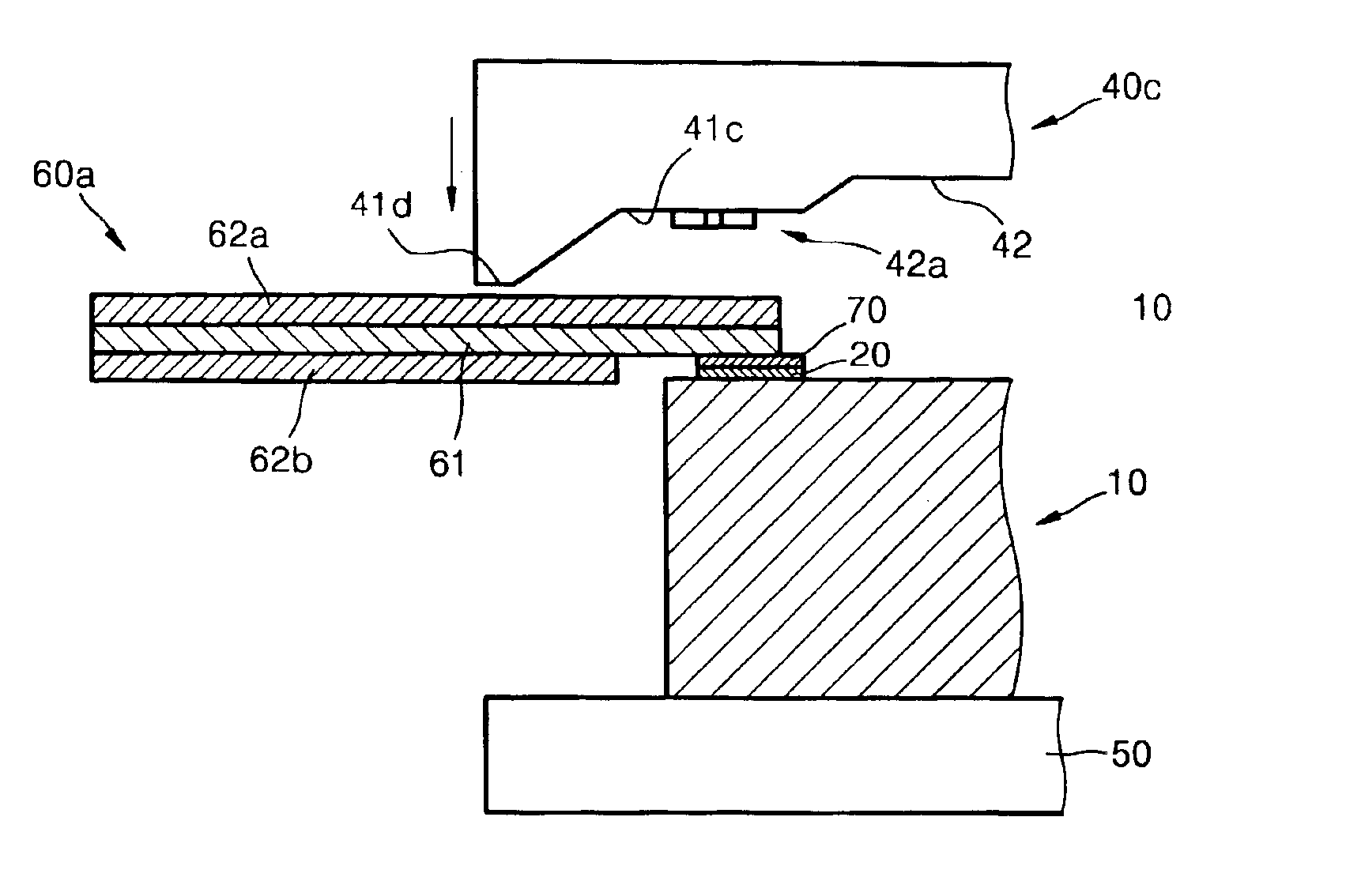
[0022]In accordance with an aspect of the present invention, there is provided an ink jet print head assembly including an ink jet print head chip and an FPC cable. The inkjet print head chip has a plurality of nozzles, from each of which an ink droplet is ejected when a corresponding respective one of a plurality of heating elements disposed within said ink jet print head assembly chip is active. The inkjet print head chip further has a plurality of bonding pads disposed thereon to provide electrical connections to said plurality of heating elements from an external electrical signal source. The FPC cable has a plurality of conductors and upper and lower films to protect the conductors. Each of the conductors has a bonding portion to be bonded to corresponding one of the pads. At least one of the conductors is hot pressure welded to at least one of the binding pads to form a bonded connection. The upper film completely covers the upper surface of the conductors, and the lower film covers the lower surface of the conductors except for the bonding portion facing the pads.

Problems solved by technology

Due to the high vibration energy required for the bonding of each conductor / pad pair, simultaneous bonding of all conductor / pad pairs may have detrimental effect on the integrity of the print head die and any other parts of the ink jet head.
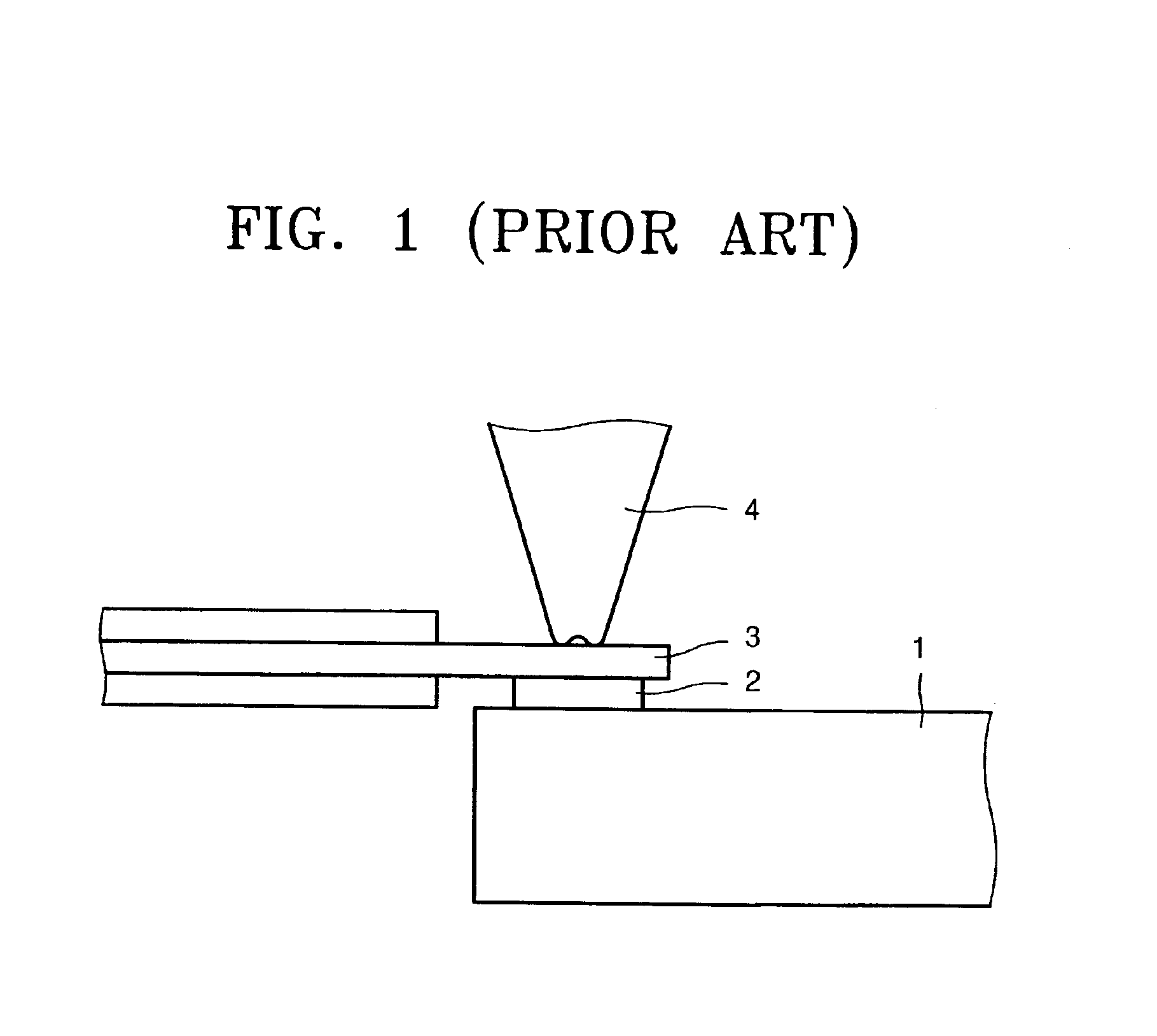
According to the conventional sequential bonding method, depending on the number of conductor / pad pairs, the bonding process takes a significant amount of time.
Moreover, after a conventional bonding process described above, a considerable length of the FPC cable is left to extend above the print head die, which blocks the travel path of a wiper in the maintenance station of the ink jet printing apparatus.
Also, when the wiper travels beyond the peripheral boundary of the print head die, the wiper continues to press on the extended portion of the FPC cable, resulting in an unnecessary shear force being applied to the bond between the print head die and the FPC cable.
Furthermore, during a conventional bonding process, the conductor of the FPC cable is completely exposed, i.e., the protective and / or insulation film covering the conductor is completely removed near the bond, requiring an excessive amount of encapsulation over the bond to insulate the exposed upper surface of the conductor.
The excessive encapsulation adds height over the bond, and thus also reduces the clearance for a wiper to travel, and increases the distance the ink droplets must travel before landing on the surface of the print medium, e.g., a sheet of paper.

Method used


Image

  • Method and apparatus for bonding a flexible printed circuit cable to an ink jet print head assembly
  • Method and apparatus for bonding a flexible printed circuit cable to an ink jet print head assembly
  • Method and apparatus for bonding a flexible printed circuit cable to an ink jet print head assembly

Examples


Embodiment Construction

[0041]Hereinafter, embodiments of the present invention will be described in detail with reference to the attached drawings. The present invention may, however, be embodied in many different forms and should not be construed as being limited to the embodiments set forth herein; rather, these embodiments are provided so that the present disclosure will be thorough and complete, and will fully convey the concept of the invention to those skilled in the art. An ink jet print head assembly is not described but will be understood through the description of bonding methods and apparatuses according to the present invention.

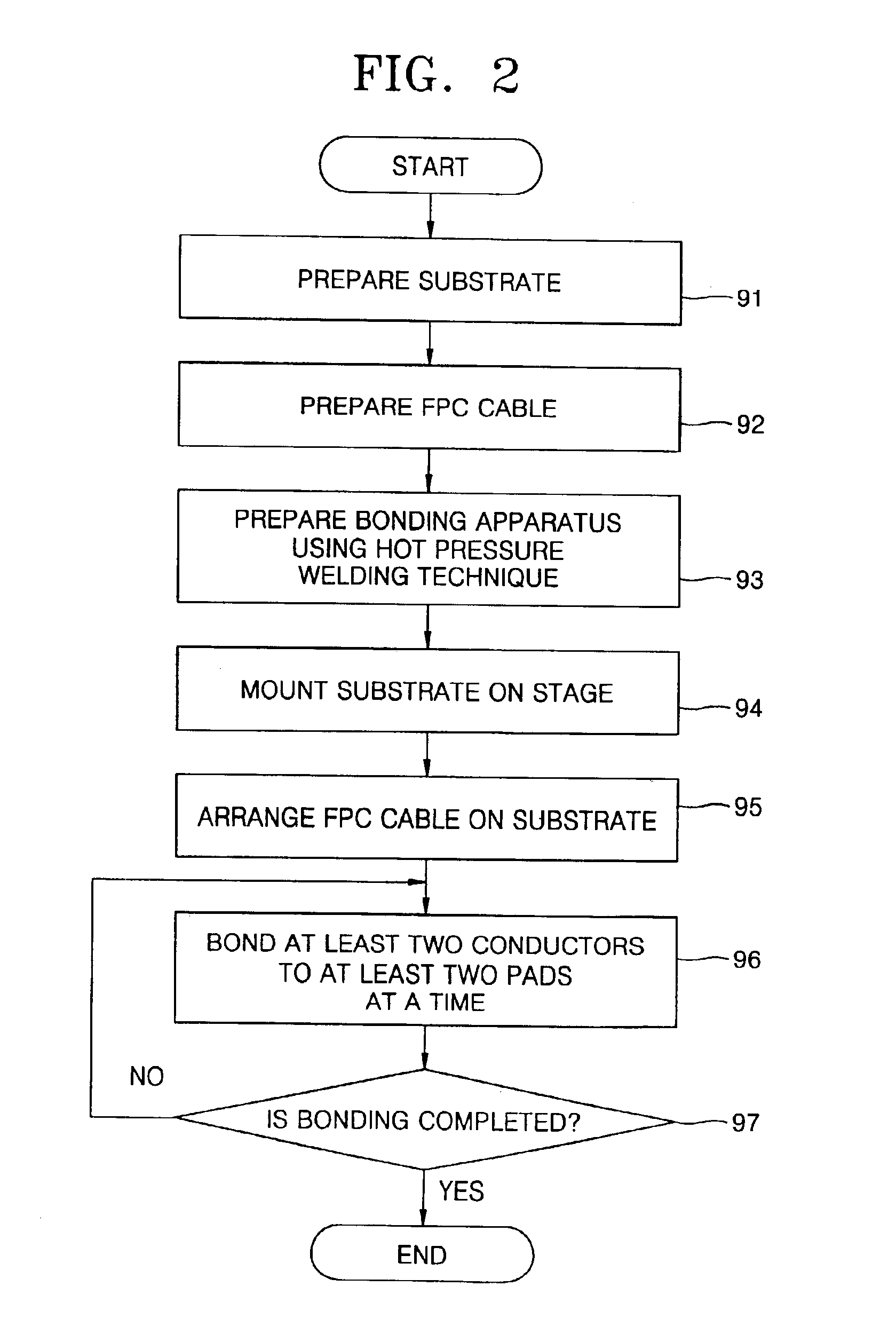
[0042]According to the principles of one aspect of the present invention, a hot pressure welding (thermo-pressure bonding) using local compressive energy may be adopted. In the hot pressure welding, a fragile print head die is not subjected to vibrational impact, so that simultaneous bonding with respect to several pads is possible in contrast with thermo-sonic bonding....


PUM


Abstract

A bonding apparatus and method thereof to bond the bonding portions of an FPC cable to pads of a print head die in order to electrically connect the print head die of an ink jet print head assembly include a stage and a bonding tool. The print head die includes resistive heaters, signal lines connected to the resistive heaters, and electrical pads to connect the signal lines to an outside of the print head die to the FPC cable having conductors having bonding portions facing the pads. The print head die is supported on the stage with the pads facing upward. The bonding tool includes a tip that press bonding portions of the FPC cable against corresponding pads of the print head die placed on the stage, and heats the bonding portions in contact with the pads to bond the bonding portion to the pads. The bonding tool includes a protrusion positioned to align with a position beyond the boundary of the print head die, and that extends lower than the tip, such that, during the bonding operation, the protrusion bends the FPC cable downward. In addition, during the bonding operation, the upper protective film of the FPC cable around the bonding portions are left intact to provide protective layer over the resulting bond, and thus results in less amount of encapsulation over the bond.

Description

CROSS-REFERENCE TO RELATED APPLICATIONS[0001]This application claims the benefit of Korean Application No. 2002-27867 filed May 20, 2002, in the Korean Intellectual Property Office, the disclosure of which is incorporated herein by reference.BACKGROUND OF THE INVENTION[0002]1. Field of the Invention[0003]The present invention relates to a method for bonding a flexible printed circuit (FPC) cable to an ink jet print head assembly, and an apparatus adopting the method.[0004]2. Description of the Related Art[0005]In an ink jet head adopting an electro-thermal transducing technique to discharge ink droplet using bubbles obtained by instantaneously heating ink, a print head die having heaters and nozzles thereon is included. The print head die also includes a plurality of signal lines electrically connected to the heaters, and a plurality of electric contact pads arranged on the peripheral edges of the print head die in an inline configuration in order to allow the signal lines to be cou...

Claims


Application Information

Patent Timeline
Patent Type & Authority Patents(United States)
IPC IPC(8): B41J2/14B41J2/045H05K3/36H05K3/32H05K1/14B41J2/16B41J2/055
CPCB41J2/14072H05K3/361H05K1/147H05K3/328H05K2203/0195H05K2201/0367H05K2201/0397B41J2/16
Inventor KIM, JEONG-SEONCHO, SEO-HYUNSON, DAE-WOOKANG, SA-YOONJUNG, MYUNG-SONG
Owner S PRINTING SOLUTION CO LTD
Learn More