Endoscope apparatus
a technology of endoscope and endoscope, which is applied in the field of endoscope apparatus, can solve the problems of inability to cope with the case in which a plurality of endoscopes are simultaneously used, and inconvenient in the prior art to selectively use a plurality of endoscopes, and achieve the effect of easy to cop
- Summary
- Abstract
- Description
- Claims
- Application Information
AI Technical Summary
Benefits of technology
Problems solved by technology
Method used
Image
Examples
first embodiment
[First Embodiment]
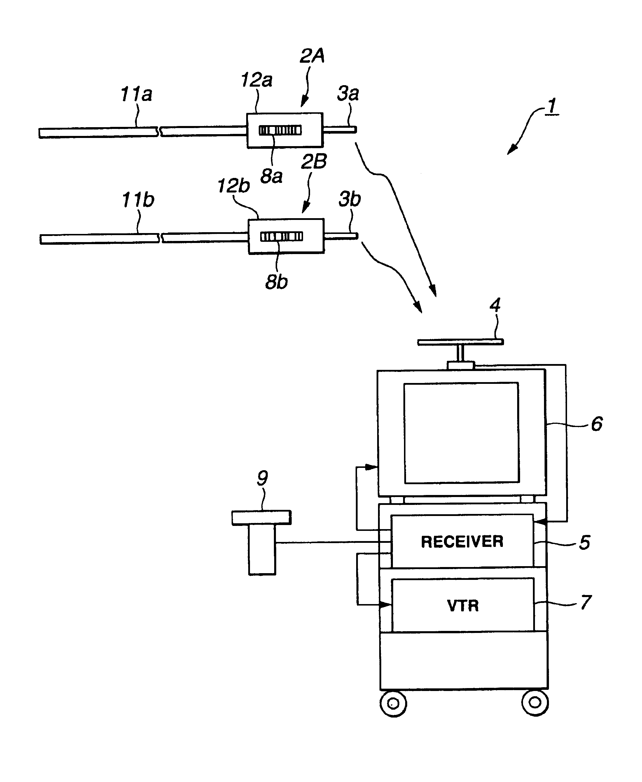
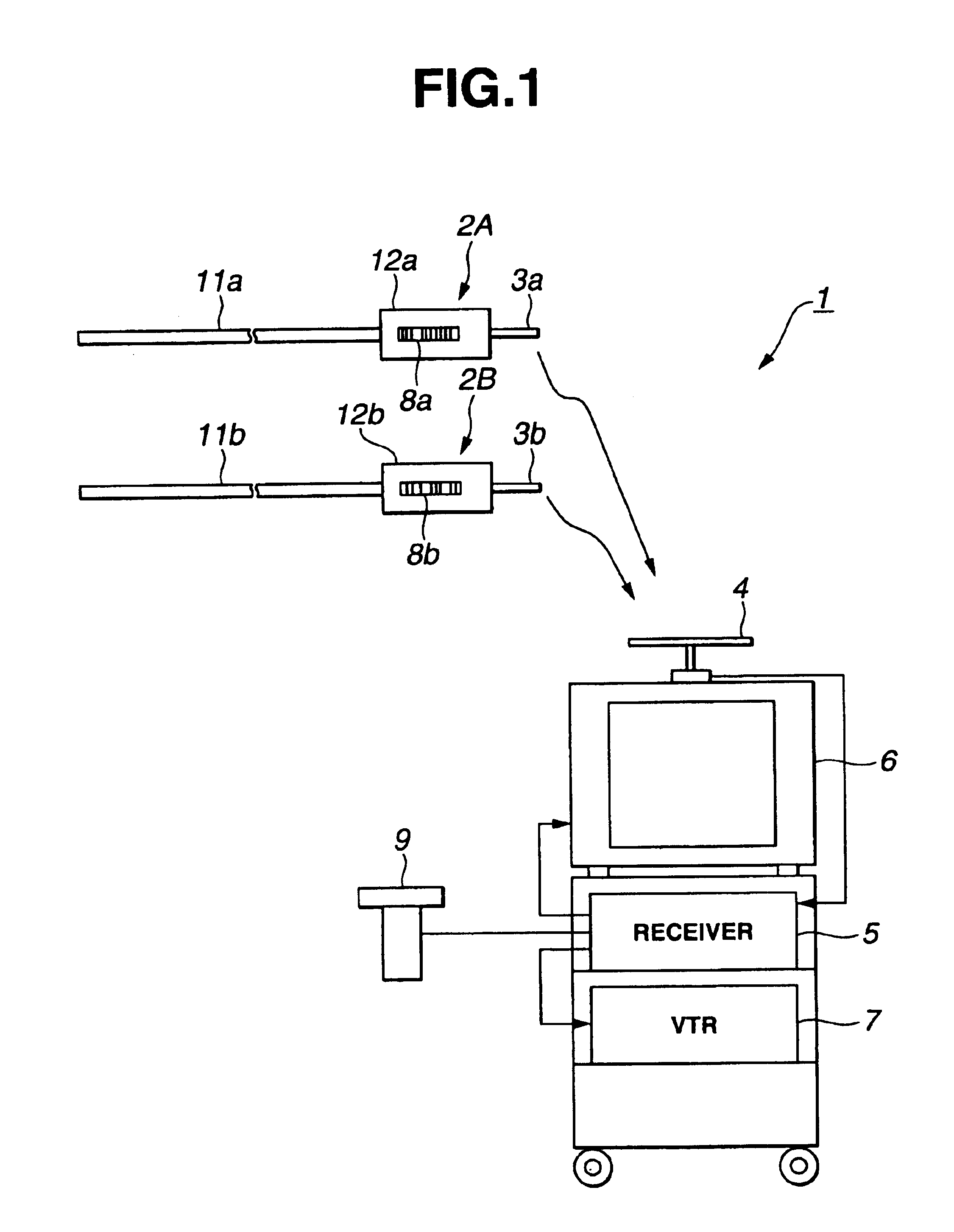
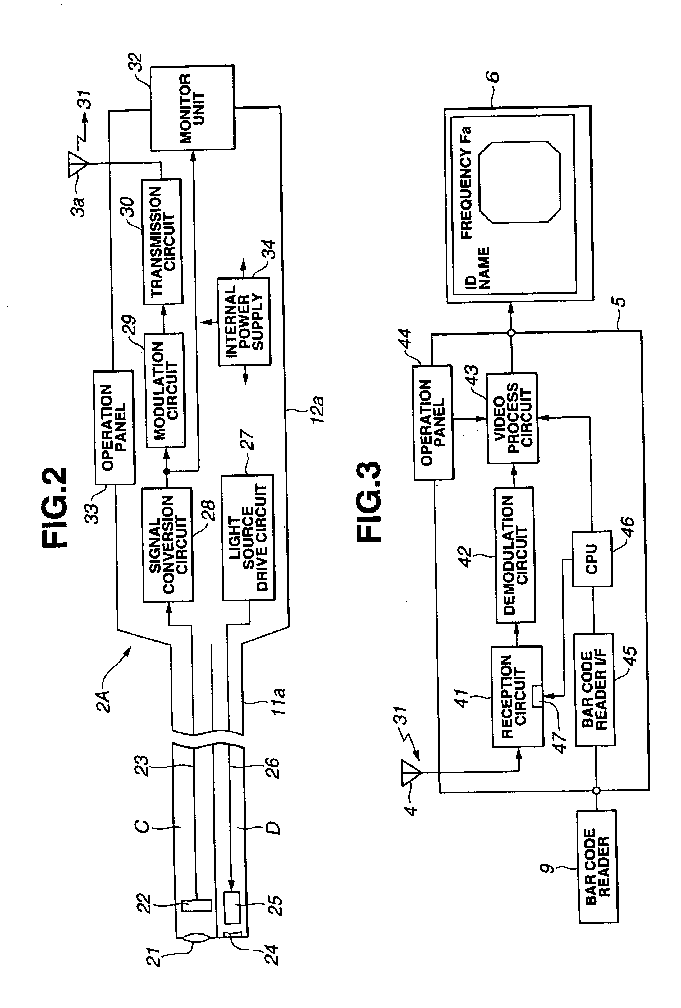
[0050]The first embodiment of the present invention will be described below with reference to FIGS. 1 to 5.
[0051]As shown in FIG. 1, an endoscope apparatus 1 according to the first embodiment of the present invention is composed of, for example, two endoscopes 2A and 2B having built-in image pickup elements respectively, a receiver (image receiver) 5 for receiving a signal transmitted from one of antennas 3a and 3b mounted respectively to the endoscopes 2A and 2B by an antenna 4 to generate a video signal, a monitor 6 for displaying the video signal generated by the receiver 5, a VTR 7 for recording the video signal, and a bar code reader 9 connected the receiver 5 for reading bar codes 8a and 8b respectively provided to the endoscopes 2A and 2B.
[0052]The endoscopes 2A and 2B have elongate insertion units 11a and 11b and operation units 12a and 12b respectively provided at the rear ends of the insertion units 11a and 11b and gripped and operated by an operator. For...
second embodiment
[Second Embodiment]
[0083]The second embodiment of the present invention will be described below with reference to FIGS. 6 and 7. In this embodiment, a plurality of transmission frequencies are set in advance such that transmission to the plurality of endoscopes is performed at the transmission frequencies. A radio wave transmitted by another endoscope is monitored, and transmission is performed at a frequency different from a frequency in use, so that interference which may occur when equal frequencies are used can be prevented.
[0084]FIG. 6 shows the internal constitution of one endoscope 2A′ in the second embodiment.
[0085]This endoscope 2A′ comprises, in addition to the components of the endoscope 2A shown in FIG. 2, a second antenna 61 and a transmission (frequency) control circuit 62 which receives a radio wave of another endoscope (referred to as 2B′) by this antenna 61 and changes and controls an oscillation frequency (carrier frequency) of a modulation circuit 29 to transmit t...
third embodiment
[Third Embodiment]
[0097]The third embodiment of the present invention will be described below with reference to FIGS. 8 and 9. This embodiment is an endoscope apparatus using optical communication.
[0098]In an endoscope apparatus 65 using optical communication shown in FIG. 8, endoscope peripheral devices are mounted on a cart 67 arranged beside an operation bed 66 in which a patient lies. On a ceiling 68, a repeating unit 69 for optical communication is arranged.
[0099]On the cart 67, an endoscope camera device 70, a VTR 71, a monitor 72, and an optical communication receiver 73 are mounted.
[0100]An endoscope 74 for performing endoscope inspection for the patient is composed of an insertion unit 75 and a main body (operation unit) 76. An optical communication transmission device 77, a light source, an image pickup device, and a battery (which are not shown) are arranged at, e.g., the rear end of the main body 76. The endoscope 74 is held by an endoscope holder 78.
[0101]The insertion ...
PUM
 Abstract
Description
Claims
Application Information
 - R&D
- Intellectual Property
- Life Sciences
- Materials
- Tech Scout
- Unparalleled Data Quality
- Higher Quality Content
- 60% Fewer Hallucinations
Browse by: Latest US Patents, China's latest patents, Technical Efficacy Thesaurus, Application Domain, Technology Topic, Popular Technical Reports.
© 2025 PatSnap. All rights reserved.Legal|Privacy policy|Modern Slavery Act Transparency Statement|Sitemap|About US| Contact US: help@patsnap.com


