Wind-power generator pod constituted by the body of an electricity generator

Inactive Publication Date: 2005-06-07
ALSTOM SA
View PDF48 Cites 65 Cited by
  • Summary
  • Abstract
  • Description
  • Claims
  • Application Information

AI Technical Summary

Benefits of technology

[0008]In a particular embodiment of the pod of the invention, the generator is coupled to the propeller via an epicyclic gearbox having inlet and outlet shafts that are on the same axis

Problems solved by technology

In particular, it is conventional to provide systems for ventilating the ins

Method used


Image

  • Wind-power generator pod constituted by the body of an electricity generator
  • Wind-power generator pod constituted by the body of an electricity generator

Examples


Embodiment Construction

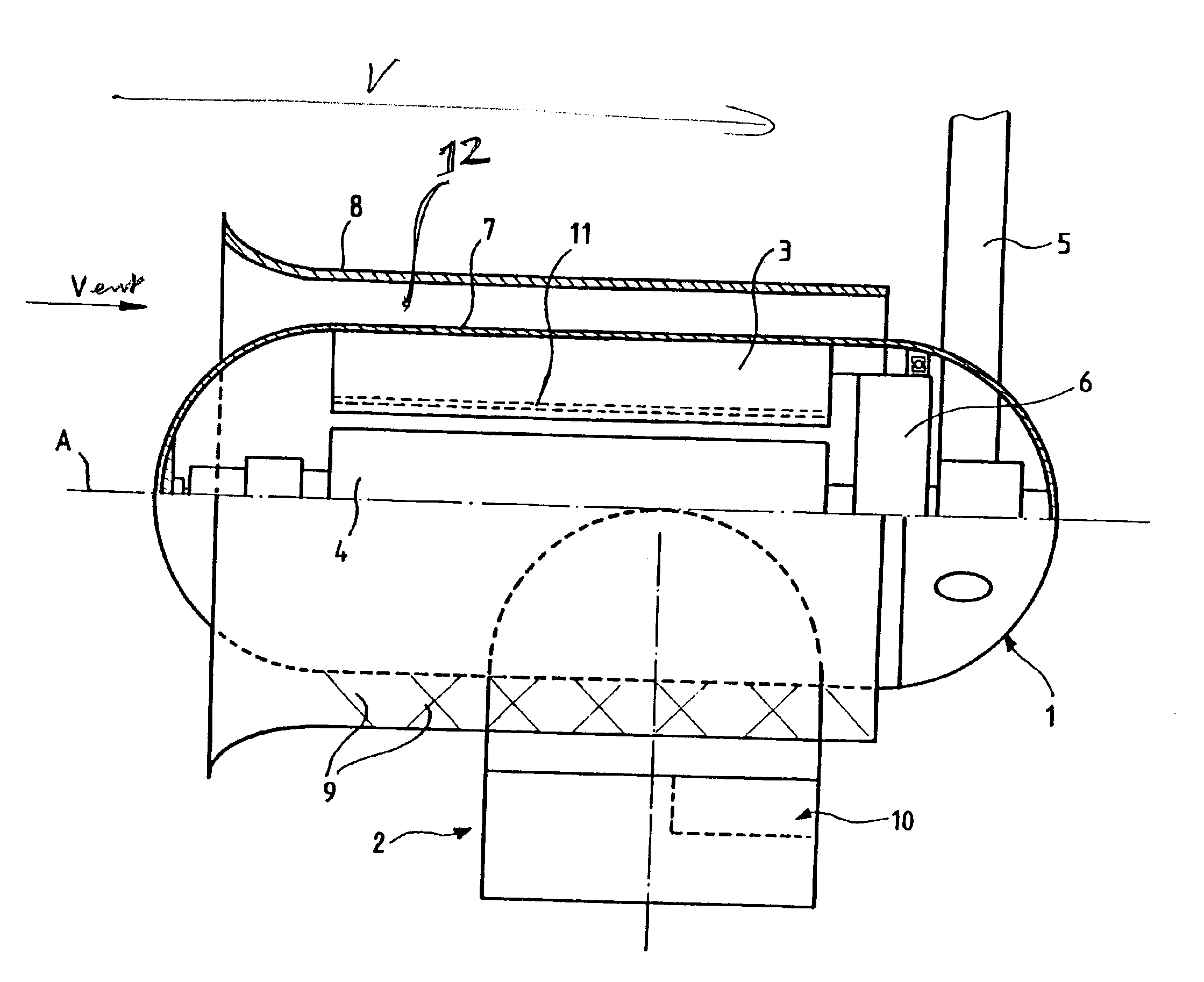
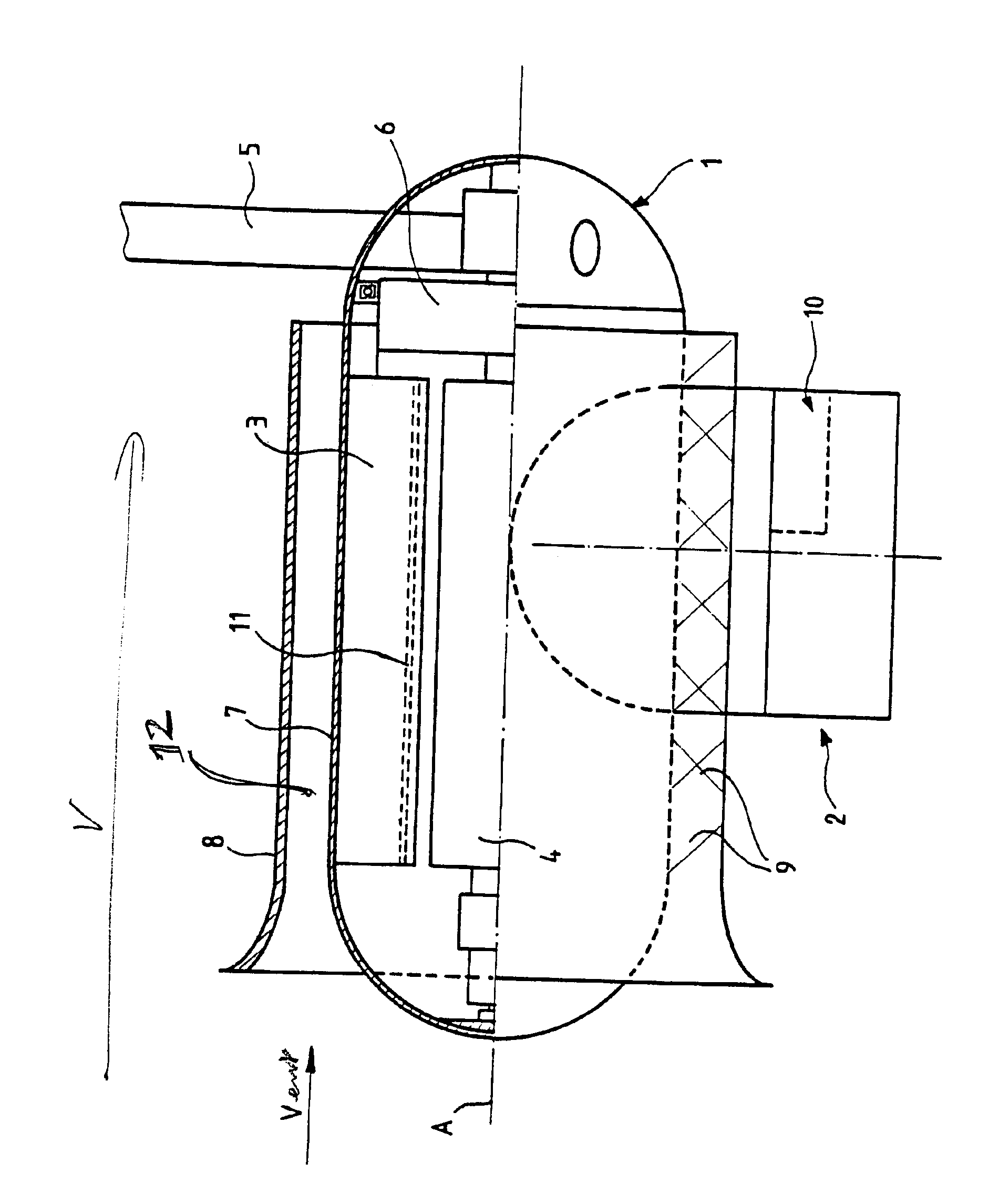
[0010]The highly diagrammatic figure shows part of a wind-power generator comprising a pod 1 mounted to swivel at the top of a vertical mast 2.

[0011]As can be seen in the figure, the pod 1 is substantially cylindrical in shape extending along an axis of revolution A that is perpendicular to the mast 2.

[0012]An electricity generator constituted by a stator 3 and a rotor 4 (shown in part in the figure above the axis A) is mounted inside the pod 1 and is coupled to a least one propeller 5 via an epicyclic gearbox (stepdown gearbox) 6.

[0013]The rigid outer fairing 7 of the pod 1 is formed by the metal body of the generator. The outer fairing 7 is surrounded coaxially by a tubular sleeve 8 which forms an annular passage 12 for the wind V driving the propeller 5. The end of the sleeve 8 facing the wind V is flared in this case and the propeller 5 is mounted at the back of the pod 1 relative to the wind direction so as to maintain a degree of stability in the flow of air along the passage ...


PUM


Abstract

The pod of wind-powered generator is constituted by a rigid fairing in which at least one electricity generator for coupling to at least one wind-driven propeller is disposed. The rigid fairing of the pod is formed by the body of the generator in which there are mounted a stator and a rotor, thereby simplifying the structure of the pod.

Description

[0001]The invention relates to a pod for a wind-power generator, the pod being constituted by a rigid fairing in which at least one electricity generator is placed for the purpose of being coupled to at least one wind-driven propeller.BACKGROUND OF THE INVENTION[0002]The fairing in a pod of that type is normally made of composite material or of metal and requires special adaptations to cool its internal elements such as the electricity generator. In particular, it is conventional to provide systems for ventilating the inside of the pod, thereby complicating its structure and increasing its weight.OBJECT AND SUMMARY OF THE INVENTION[0003]The object of the invention is to remedy that drawback.[0004]According to the invention, the rigid fairing of the pod is formed by the body of the generator in which a stator and a rotor are mounted. This generator body can advantageously contain the gearing of the gearbox and the mechanism for steering the pod, thereby making the pod of the wind-pow...

Claims


Application Information

Patent Timeline
IPC IPC(8): F03D9/00H02K9/14H02K9/00H02K7/18H02K5/20
CPCF03D9/002H02K7/1838H02K9/14F05B2260/20H02K1/20Y02E10/725Y02E10/726H02K5/20F03D9/25F03D13/20Y02E10/72Y02T50/60H02K5/207
Inventor MERCIER, JEAN-CHARLESFERON, STEPHANE
Owner ALSTOM SA
Why Eureka
Try Eureka