Method for driving plasma display panel

a technology of display panel and plasma, which is applied in the direction of static indicating devices, instruments, electrodes, etc., can solve the problems of increasing electric power consumption and increasing electric power consumption, and achieve the effects of improving the stability (i.e., the operation margin) of the display luminous discharge, improving the contrast of the lights-out cells, and improving the stability

Inactive Publication Date: 2005-06-07
HITACHI LTD
View PDF15 Cites 22 Cited by
  • Summary
  • Abstract
  • Description
  • Claims
  • Application Information

AI Technical Summary

Benefits of technology

[0034]From the above, in the all write-in period, except for at least one of the sub-field of the plural numbers thereof, due to collaboration with the erase period, the contrast can be improved by only using the self-erase electrode, but without generating the initial discharge. In the address period, selection of the lights-out cell by using the method of erasing the wall charge, and also by using the surface current accompanying with no light-emission in the place of the discharge current, with fully utilizing the structure that the A and Y electrodes are formed on the same plane, ena

Problems solved by technology

For the purpose of an increase in the brightness mentioned above, for example, voltage of the sustain pulses must be made high enough, therefore it results in an increase of electric power consumption, incidentally.
In particular,

Method used


Image

  • Method for driving plasma display panel
  • Method for driving plasma display panel
  • Method for driving plasma display panel

Examples


first embodiment

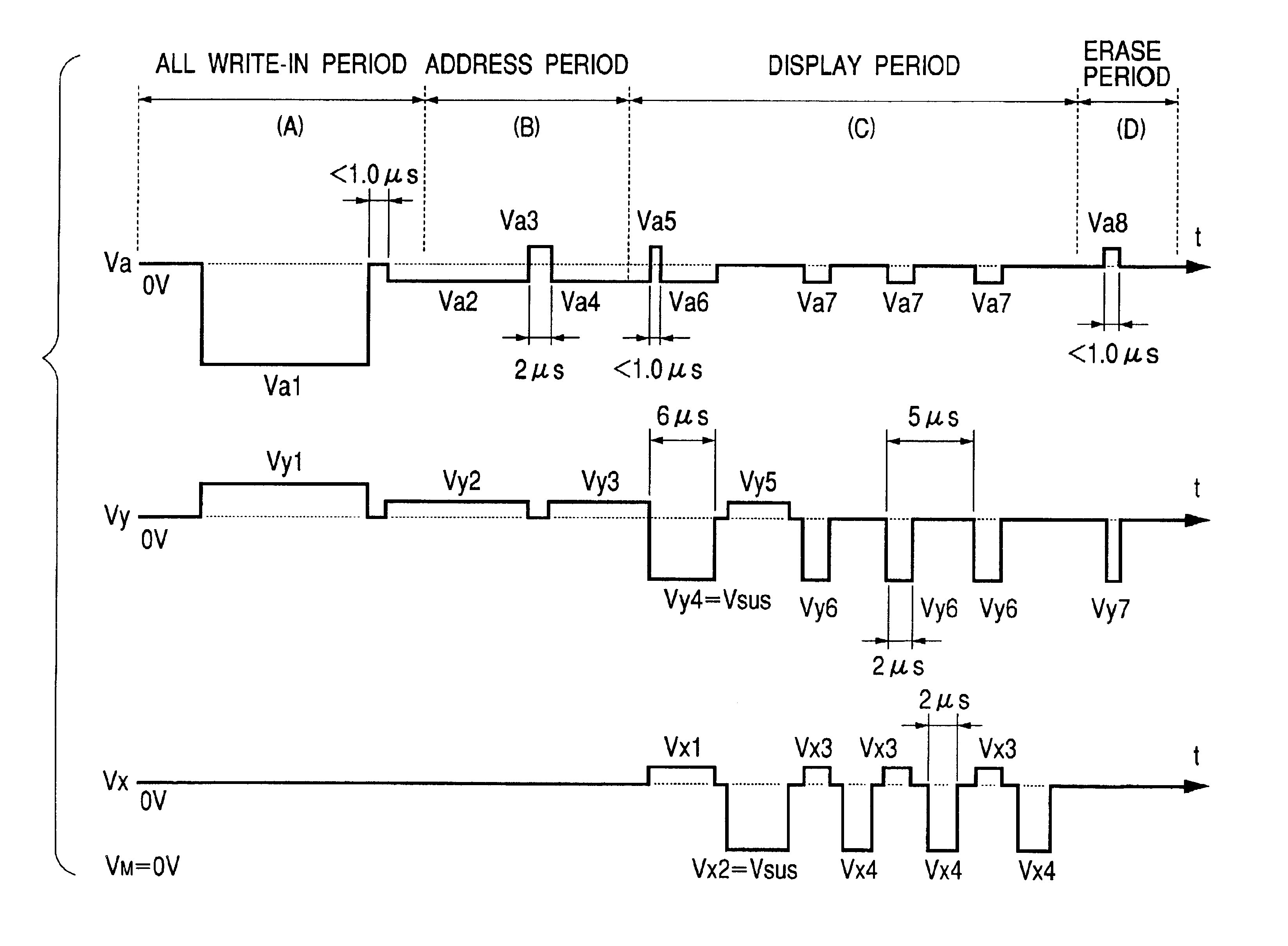
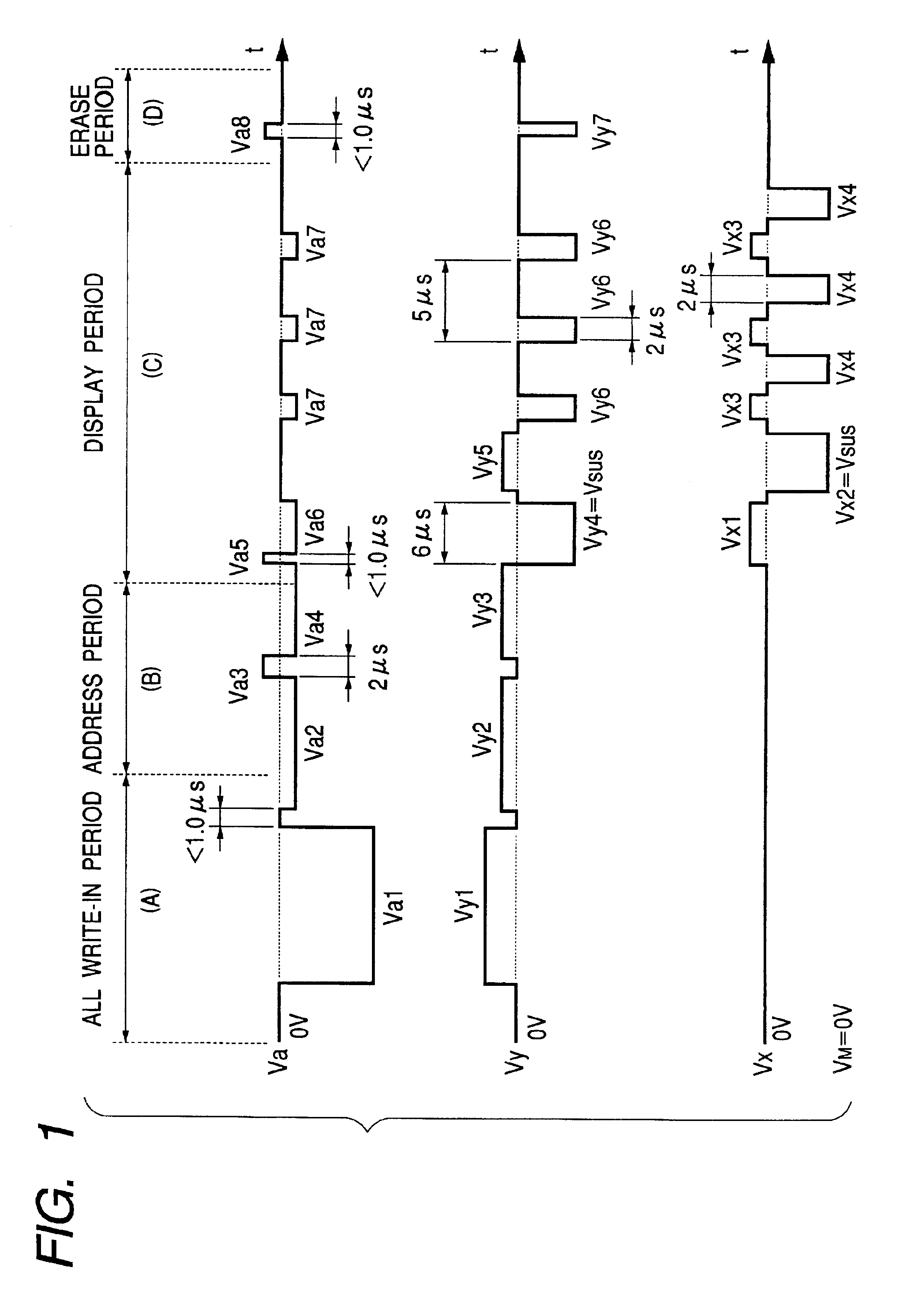
[0046]FIGS. 1 to 6 are views for explaining a first embodiment according to the present invention.

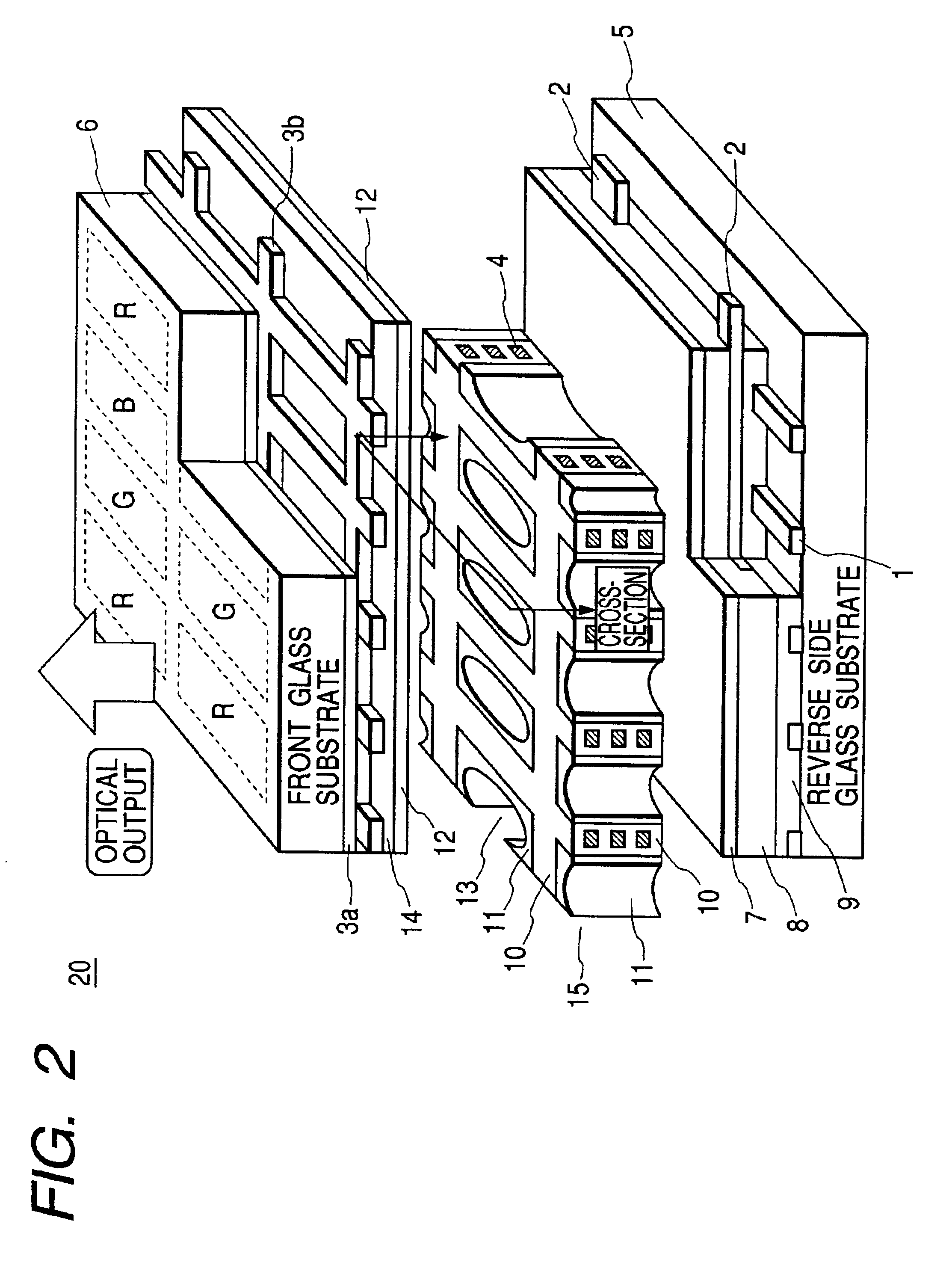
[0047]FIG. 1 is a view of driving waveforms; FIG. 2 a perspective view of a plasma display panel; FIG. 3 is a cross-section of that panel; FIG. 4 the structural view of a display apparatus having the plasma display panel; FIGS. 5(a) and 5(b) views for explanation on the principle of the display discharge; and FIG. 6 a view for showing the operation margin between addressing voltage and sustain voltage in the display of static picture.

[0048]The present embodiment is an embodiment for carrying out the panel driving with using novel driving waveforms.

[0049]In FIG. 2, a reference numeral 1 indicates address electrodes for conducting addressing; 2 first display electrodes (i.e., Y electrodes) for conducting display, being provided intersecting with the address electrodes 1 at about right angles; 3a a flat electrode of second display electrodes (i.e., X electrodes) for conducting display in c...

third embodiment

[0069]FIGS. 8 and 9 are views for explaining a third embodiment according to the present invention.

[0070]FIG. 8 shows an example of the cross-section structure of the plasma display panel used in the present third embodiment. In this FIG. 8, a reference numeral 65 indicates an address electrode for addressing; 68 a first display electrode (i.e., the Y electrode) being provided crossing with the address electrode at the right angles for displaying; 69 a second display electrode disposed nearly on the same plane with the first display electrode 68 and also in parallel therewith, for displaying in collaboration with the first display electrode 68; 58 a flat electrode formed from a light-transmission member or material in a plane-like shape; 59a and 59b buss electrodes piled on the flat electrode 58 and formed nearly in parallel with the first display electrode 68; 74 a partition wall provided in the lattice-like form between the side, on which the first display electrode (i.e., the Y e...


PUM


Abstract

In a driving method for driving a plasma display panel, achieving improvements on luminous efficiency, brightness and contrast, as well as, low voltage and low power consumption, and also high-speed addressing and sustain therewith, wherein onto a second display electrode is applied pulse voltage in reverse polarity with sustain pulse voltage, nearly in synchronism with the sustain pulse voltage to be applied onto a first display electrode, thereby shifting initial discharge (or, pre-charge) caused between the first display electrode and a metal electrode of a partition portion after the generation thereof into display discharge, thereby forming wall charge and wall voltage on the second display electrode.

Description

BACKGROUND OF THE INVENTION[0001]1. Field of the Invention[0002]The present invention relates to a method for driving a plasma display panel, and also a driving circuit and a display apparatus using thereof.[0003]2. Description of Prior Art[0004]Conventionally, in the structure of an AC type plasma display apparatus having three electrodes, for example, the display panel is built up with electrodes for use in addressing (i.e., address electrodes) and two (2) kinds of electrodes for use in discharging for display (i.e., X electrodes and Y electrodes) aligned within the same plane, but being disposed on the respective substrates opposing to each other, separately. In driving for displaying a picture thereon, after conducting initialization upon cells by applying initialization pulses onto the two (2) kinds of display electrodes (thus, the X electrodes and the Y electrodes), addressing is conducted corresponding to the picture signal, by applying both addressing pulses and scanning pul...

Claims


Application Information

Patent Timeline
IPC IPC(8): G09G3/28G09G3/20G09G3/288G09G3/291G09G3/292G09G3/294G09G3/297G09G3/298H01J11/12H01J11/14H01J11/16H01J11/22H01J11/24H01J11/26H01J11/32H01J11/34H01J11/36
CPCG09G3/2986G09G3/296
Inventor AKIBA, YUTAKA
Owner HITACHI LTD
Why Eureka
Try Eureka