Scrubber with sonic nozzle

Inactive Publication Date: 2005-06-14
APPLIED MATERIALS INC
View PDF25 Cites 25 Cited by
  • Summary
  • Abstract
  • Description
  • Claims
  • Application Information

AI Technical Summary

Problems solved by technology

Although such devices may remove the majority of slurry and other particulates from a substrate's surfaces, often residual slurry and other particulates may remain particularly along a substrate's beveled edge, where scrubber brushes and sonic fluid sprays may not uniformly contact the substrate's surface.

Method used


Image

  • Scrubber with sonic nozzle
  • Scrubber with sonic nozzle
  • Scrubber with sonic nozzle

Examples


Embodiment Construction

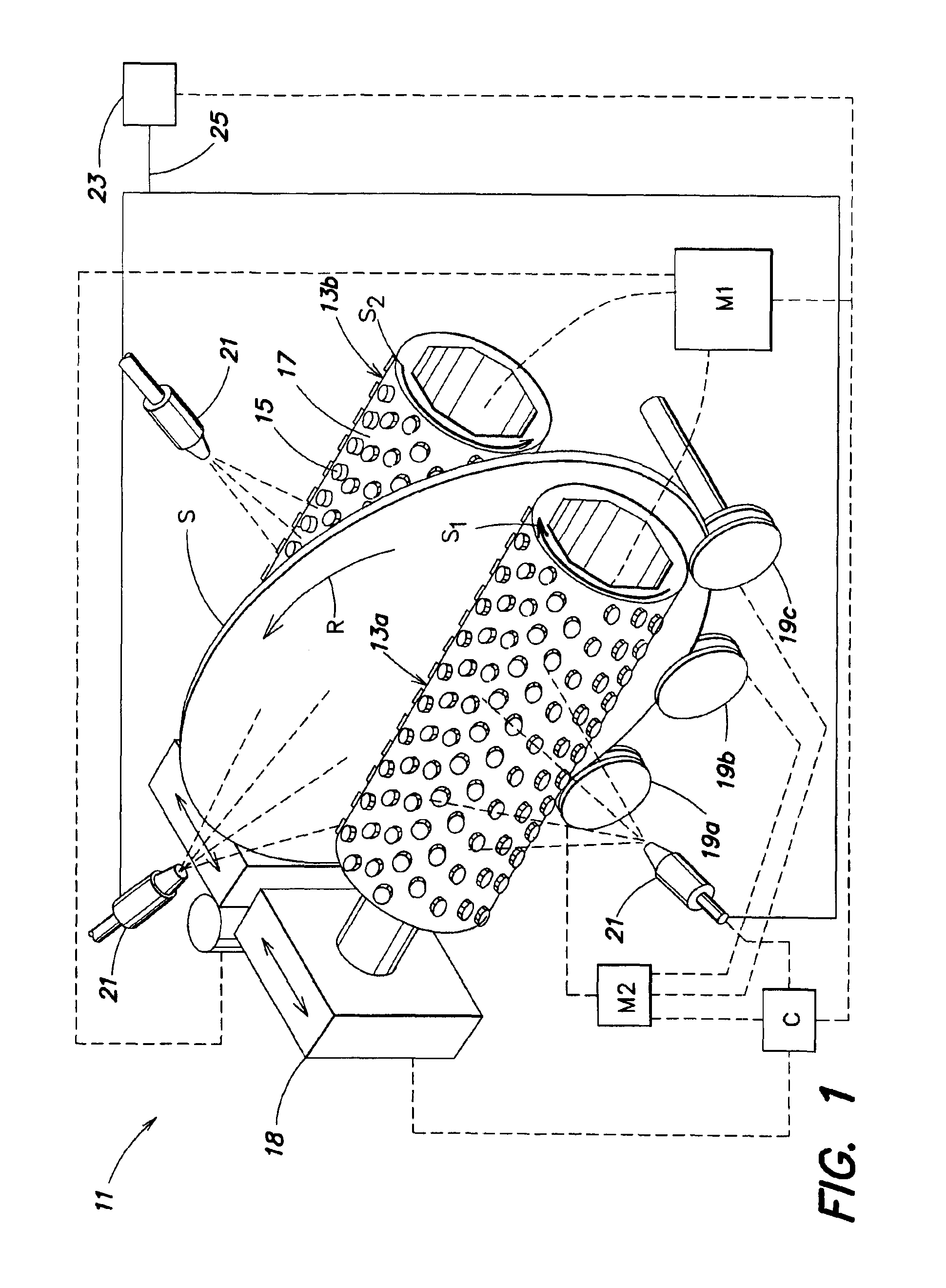
[0012]FIG. 1 is a side perspective view of one embodiment of an inventive scrubbing device 11 that may perform the inventive scrubbing method. The inventive scrubbing device 11 comprises a pair of PVA brushes 13a, 13b. Each brush may comprises a plurality of raised nodules 15 across the surface thereof, and a plurality of valleys 17 located among the nodules 15. The PVA brushes 13a, 13b may be supported by a pivotal mounting (represented generally by reference number 18) adapted to move the PVA brushes 13a, 13b into and out of contact with the substrate S supported by the substrate support 19, thus allowing the PVA brushes 13a, 13b to move between closed and open positions so as to allow a substrate S to be extracted from and inserted therebetween.

[0013]The scrubber device 11 also comprises a substrate support 19 adapted to support and further adapted to rotate a substrate S. In one aspect, the substrate support 19 may comprise a plurality of rollers 19a-c each having a groove adapt...


PUM


Abstract

An apparatus for cleaning a substrate is provided. The apparatus comprises a plurality of rollers adapted to support a substrate in a vertical orientation, a scrubber brush adapted to contact a substrate supported by the plurality of rollers, and a sonic nozzle positioned at an elevation below the elevation of the scrubber brush and adapted so as to output a sonicated fluid spray that contacts a beveled edge or a major surface of the substrate such that fluid having sufficient sonic energy to harm the scrubber brush will not contact the scrubber brush.

Description

FIELD OF THE INVENTION[0001]The present invention relates to apparatuses and methods adapted to scrub thin substrates or substrates such as semiconductor substrates, compact discs, glass substrates, and the like. More particularly, the present invention relates to a method of sonically cleaning a substrate in an apparatus adapted to scrub a vertically oriented substrate.BACKGROUND OF THE INVENTION[0002]During formation of a semiconductor device, various layers (e.g. oxides) require planarization to remove steps or undulations prior to formation of subsequent layers. Planarization is typically performed mechanically by forcing a semiconductor substrate face down against a semi-porous polishing pad which is saturated with an abrasive compound (i.e., a slurry) and by rotating the polishing pad relative to the semiconductor substrate. The slurry reacts with the substrate's surface, which makes the surface easier to remove, and the rotary motion between the polishing pad and the substrat...

Claims


Application Information

Patent Timeline
Patent Type & Authority Patents(United States)
IPC IPC(8): B08B3/02B08B1/04H01L21/00
CPCB08B1/04B08B3/02H01L21/67046Y10S134/902B08B2203/0288
Inventor SUGARMAN, MICHAEL
Owner APPLIED MATERIALS INC
Why Eureka
Try Eureka