
Flow rate measurable air intake duct throttling device

A throttling device and air inlet technology, which is applied in the field of throttling devices with measurable flow rate, can solve the problems of many pressure measuring points, flow field distortion, sensitive throttling effect, etc., and achieve the effect of small measurement error and shortened length

Active Publication Date: 2017-02-22
NAT UNIV OF DEFENSE TECH
View PDF7 Cites 7 Cited by
  • Summary
  • Abstract
  • Description
  • Claims
  • Application Information

AI Technical Summary

Problems solved by technology

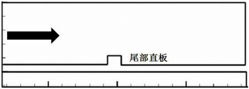
For sloping and straight boards ( figure 2 , image 3 ), the throttling devices are all on the side of the flow channel. Under the condition of asymmetric incoming flow, the boundary layer on the side of the throttling device is more sensitive to the throttling effect, so this kind of throttling device is not convenient for test operation
In addition, in the inlet test, it is necessary to accurately simulate different changes in back pressure (such as back pressure change rate, back pressure change path, etc.), and the current throttling device is difficult to meet the requirements
The current flow measuring device requires more pressure measuring points in the "meter" character arrangement
Moreover, due to the change of the angle of attack of the inlet, flow separation occurs inside the inlet, resulting in distortion of the flow field, and there is a large error in the flow obtained by using the "meter" character

Method used


Image

  • Flow rate measurable air intake duct throttling device
  • Flow rate measurable air intake duct throttling device
  • Flow rate measurable air intake duct throttling device

Examples


Embodiment Construction

[0038] The present invention will be further described below in conjunction with the accompanying drawings and specific embodiments.

[0039] refer to Figure 5 and Figure 6 , the present invention provides a schematic structural diagram of an air inlet throttling device with measurable flow rate. It includes a throttling butterfly valve 1, a throttling butterfly valve driving mechanism, a throttling cylinder 2 and a sonic nozzle 3. A throttling butterfly valve 1 is vertically inserted in the throttling cylinder 2 relative to its axis, and the throttling butterfly valve driving mechanism is arranged on On the outside of the throttling cylinder 2, the throttle butterfly valve 1 is driven by the throttling butterfly valve drive mechanism to rotate and then change the blockage area in the throttle cylinder to adjust the back pressure. The sonic nozzle 3 is installed on the throttle cylinder 2 the export port. By arranging the sonic nozzle downstream of the throttling device, ...


PUM


Abstract

The invention discloses a flow rate measurable air intake duct throttling device, comprising a throttling butterfly valve, a throttling butterfly valve driving mechanism, a throttling cylinder and a sonic nozzle, wherein the throttling butterfly valve is vertically inserted into the throttling cylinder relative to the axis, the throttling butterfly valve driving mechanism is arranged outside the throttling cylinder, the throttling butterfly valve rotates under the drive of the throttling butterfly valve driving mechanism to change the blocking area in the throttling cylinder so as to adjust the magnitude of negative pressure, and the sonic nozzle is installed at the outlet end of the throttling cylinder. The throttling butterfly valve in the device is subjected to a relatively small aerodynamic resistance torque, so that the required power of a driving motor is relatively low; the motor for driving the throttling butterfly valve to rotate is installed outside a runner, so that the length of the throttling device is greatly shortened. The throttling device connected in series with the sonic nozzle can obtain the flow rate of an air intake duct in real time while adjusting the negative pressure at the outlet of the air intake duct, and has small measurement error.

Description

technical field [0001] The invention relates to the field of air inlet wind tunnel tests, in particular to a throttling device with measurable flow rate. Background technique [0002] The scramjet engine is mainly composed of intake port-isolation section, combustion chamber and tail nozzle. The intake port-isolation section is an important compression part of the engine, and can effectively prevent the influence of downstream combustion chamber back pressure on upstream flow . The anti-backpressure capability of the inlet-isolating section is an important parameter to evaluate its performance. In the wind tunnel test, in order to simulate the influence of the back pressure of the combustion chamber, a throttling device is usually arranged at the end of the intake port-isolating section, and the change of the back pressure is simulated by adjusting the throttling degree. When studying the non-starting process of the intake port, it is usually necessary to measure the flow ...

Claims


Application Information

Patent Timeline
IPC IPC(8): G01M9/00
CPCG01M9/00
Inventor 范晓樯熊冰陶渊赵健周鑫
Owner NAT UNIV OF DEFENSE TECH
Learn More