Supersonic nozzle preventing from slag entrapment

A supersonic, anti-rolling slag technology, applied in the field of injection devices, can solve problems such as endangering production safety and life safety, and achieve the effects of improving oxygen utilization rate, promoting steel slag reaction, and enhancing penetrating ability

Active Publication Date: 2016-03-23
CISDI ENG CO LTD
View PDF11 Cites 8 Cited by
  • Summary
  • Abstract
  • Description
  • Claims
  • Application Information

AI Technical Summary

Problems solved by technology

Due to the same mechanism, the steel slag is easily adsorbed on the gun head, and even

Method used


Image

  • Supersonic nozzle preventing from slag entrapment
  • Supersonic nozzle preventing from slag entrapment
  • Supersonic nozzle preventing from slag entrapment

Examples


Embodiment 1

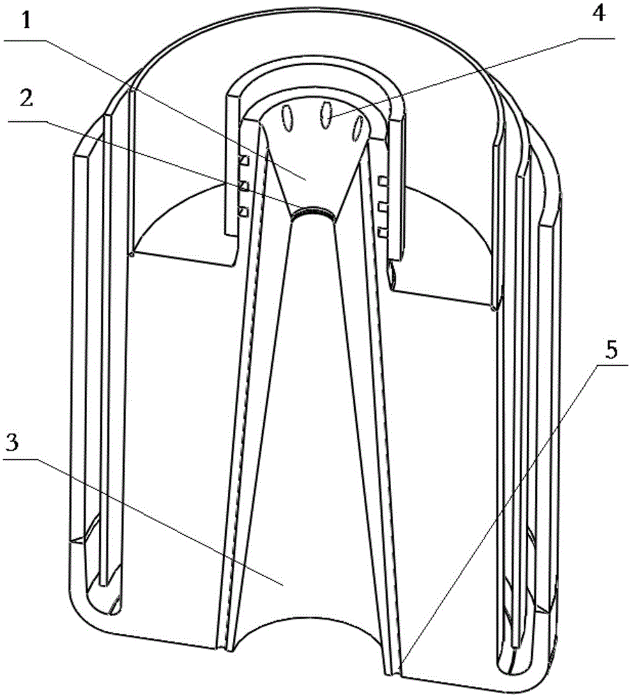
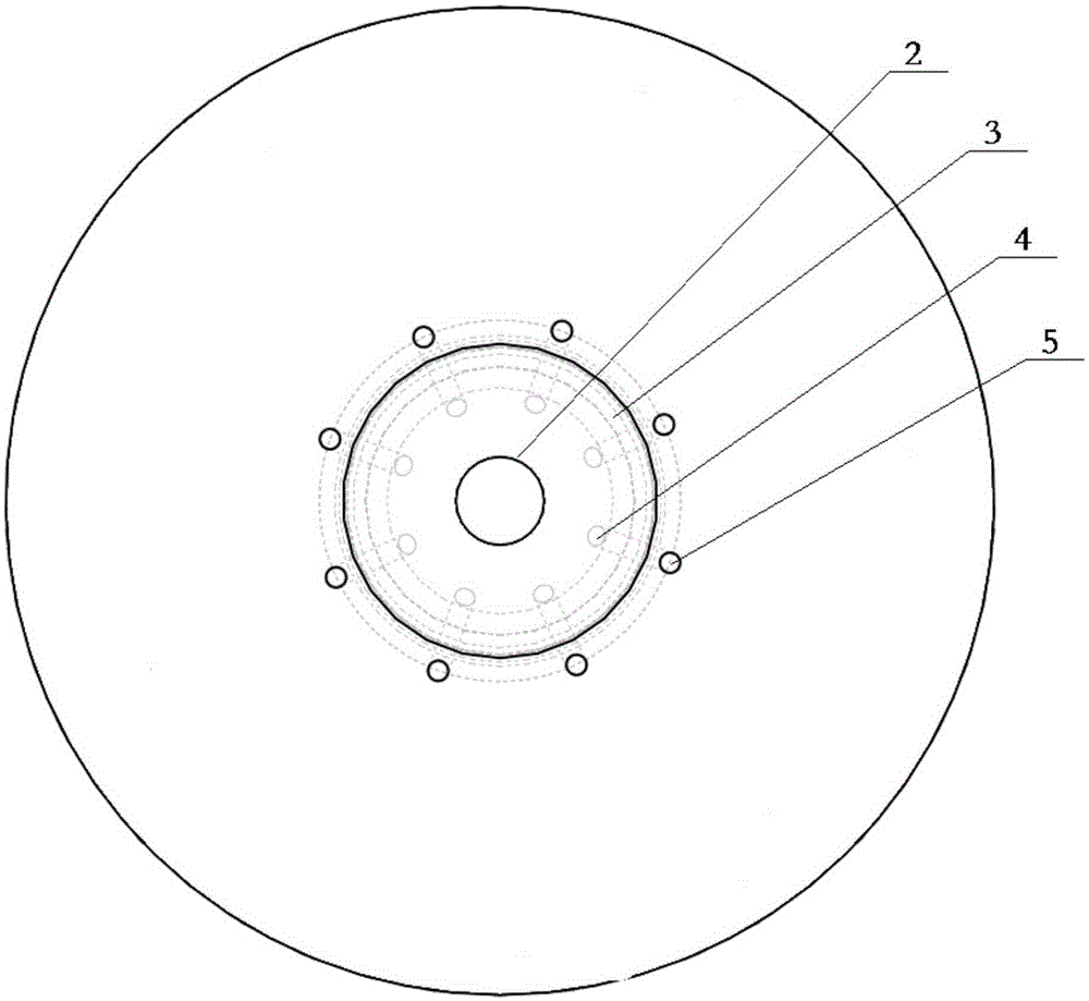
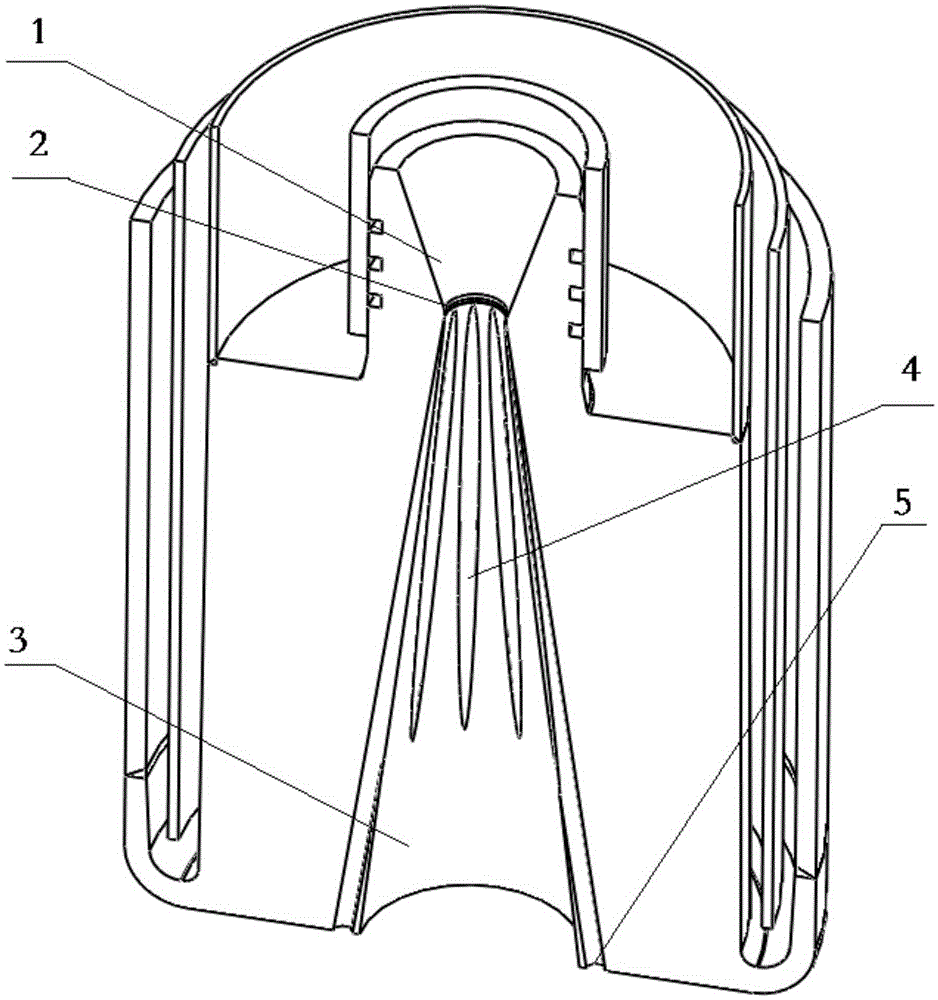
[0035] Such as Figure 1 to Figure 5 As shown, it is an anti-slag entrainment supersonic nozzle applied to the RH top gun. Its main structure is a single-hole Laval nozzle, including the main oxygen channel and the auxiliary oxygen channel. The main oxygen channel is formed by the center of the supersonic Laval tube. Holes are formed, and the auxiliary oxygen channel is a slender orifice on the periphery of the center hole of the supersonic Laval tube; the Laval tube is divided into an inlet contraction section 2, a throat constant velocity section 2, and an outlet expansion section 3 along the airflow direction. ; The inlet contraction section 2 compresses and accelerates the airflow, the throat constant velocity section 2 airflow reaches the speed of sound, and the outlet expansion section 3 accelerates the airflow to supersonic speed. Of course, it also includes structures such as water-cooled outer pipes, water risers, and water-cooled inner pipes. Oxygen with a certain p...

Embodiment 2

[0042] Such as Image 6As shown, a porous anti-slag entrainment supersonic nozzle applied to a converter oxygen lance, its main body is a porous Laval nozzle structure, with a plurality of Laval nozzle holes, each of which is surrounded by a Laval nozzle hole. A plurality of throttle holes are provided, and the Laval-type nozzle holes form a main oxygen channel, and the peripheral oxygen channel is formed by a corresponding throttle hole on the periphery of each main oxygen channel. Multiple Laval nozzles simultaneously inject oxygen into the molten steel bath of the converter. For each Laval nozzle, there is a main oxygen channel and a secondary oxygen channel. The main oxygen channel of the nozzle is the central hole channel of the supersonic Laval tube, and the secondary oxygen channel is the slender orifice on the periphery of the supersonic Laval tube. , in this example, the orifice air inlet 4 is at the entrance of the Laval pipe, and the orifice air outlet 5 is around ...


PUM


Abstract

The invention provides a supersonic nozzle preventing from slag entrapment, belonging to the field of steel making. The supersonic nozzle is composed of a main oxygen channel and an auxiliary oxygen channel positioned on the periphery of the main oxygen channel, wherein a center hole of a Laval tube forms the main oxygen channel, a plurality of narrow-long orifices are formed in the Laval tube, and the orifices are positioned in the periphery of the center hole and form the auxiliary oxygen channel. An auxiliary oxygen flow forms a surrounded accompanying flow outside a central supersonic jet flow, a low pressure area generated by the supersonic jet flow is weakened and canceled, and the suction enabling steel slag to be involved in the nozzle is eliminated; meanwhile, the expansion and attenuation of the central supersonic jet flow can be much smaller, the supersonic jet flow is longer, and the penetration depth and the stirring intensity of the oxygen jet flow for a molten pool are improved; the gun position is heightened so that liquid steel splash and slag bonding of a gun head are reduced, and the service life is prolonged. In the RH vacuum refining process, the main oxygen flow impacts liquid steel and reacts with carbon in the liquid steel to generate carbon monoxide, the carbon monoxide overflowing the liquid steel generates secondary combustion with the auxiliary oxygen flow of the surrounded accompanying flow to heat a vacuum tank, and the temperature drop of liquid steel is reduced.

Description

technical field [0001] The invention relates to an injection device for generating a supersonic long oxygen flow in the metallurgical industry, in particular to a supersonic nozzle for preventing slag entrainment. Background technique [0002] RH vacuum refining is a iron and steel metallurgy technology developed in the 1950s. In addition to vacuum degassing, it can also decarburize by blowing oxygen and desulfurize by spraying powder, which enables large-scale smelting of ultra-low carbon clean steel. The oxygen blowing and decarburization device is first installed in the lower part of the vacuum tank, then in the middle of the vacuum tank, and finally in the top of the vacuum tank to become a water-cooled multifunctional top gun. 现有技术中,无论是RH-KTB顶枪、RH-MFB顶枪、RH-MESID顶枪、RH-PB顶枪还是中国专利申请号200420027046.4、200610076151.0、200820174977.5、200820174973.7、201110000083.0、201210346652.1、201310431081.6所涉及 The top gun or nozzle of the sprayer adopts a round-hole Laval tube structure. In the ...

Claims


Application Information

Patent Timeline
IPC IPC(8): C21C7/068C21C7/10
CPCC21C7/068C21C7/10
Inventor 刘向东王翔钟渝任鲲先潘光明
Owner CISDI ENG CO LTD
Why Eureka
Try Eureka