
Integrated circuit chip handling apparatus and method

a technology for integrated circuit chips and apparatuses, applied in the direction of metal-working machine components, instruments, manufacturing tools, etc., can solve the problems of re-testing of chips, damage of chips, and insufficient practi

Inactive Publication Date: 2005-06-14
MEI CALIFORNIA
View PDF86 Cites 11 Cited by
  • Summary
  • Abstract
  • Description
  • Claims
  • Application Information

AI Technical Summary

Benefits of technology

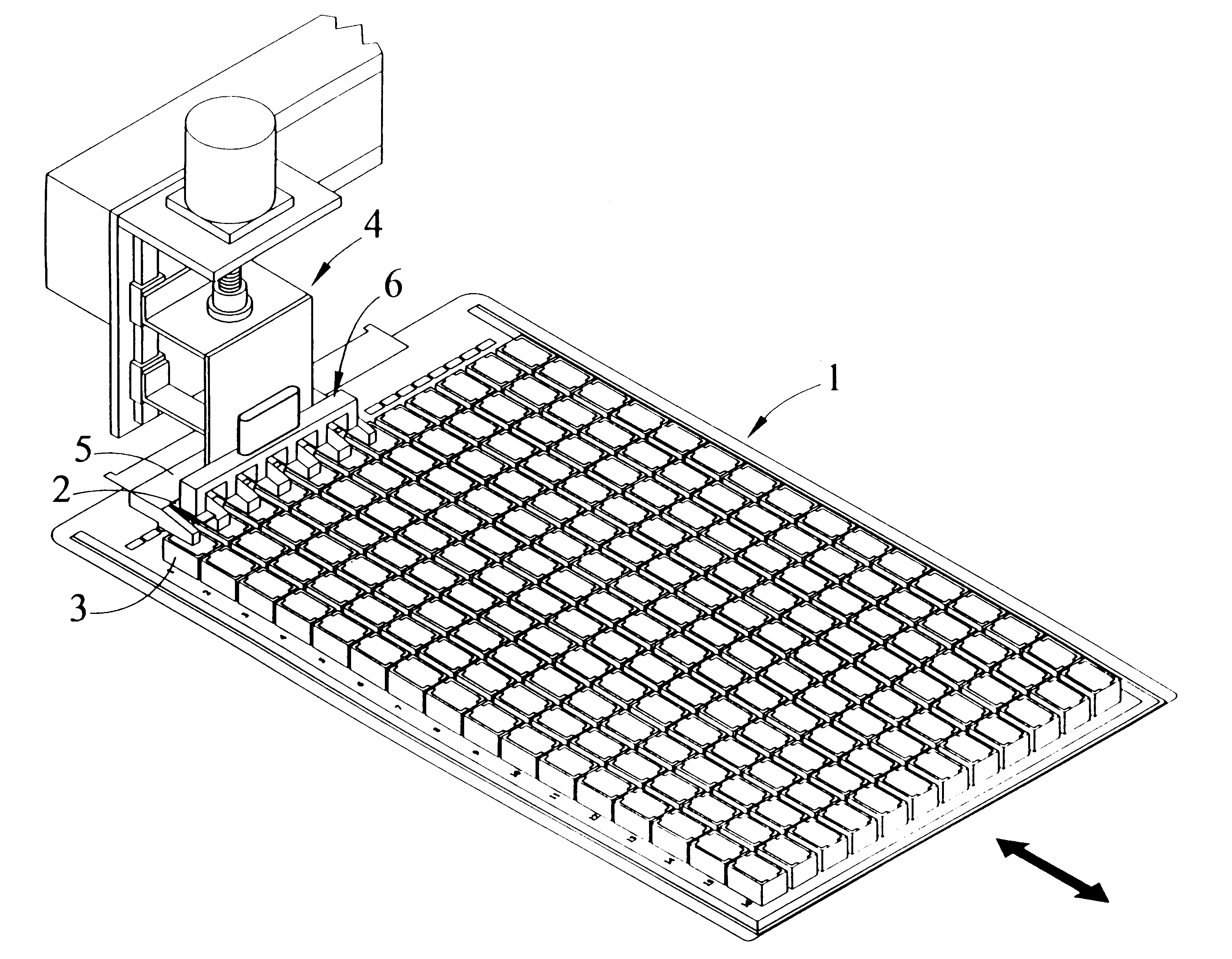
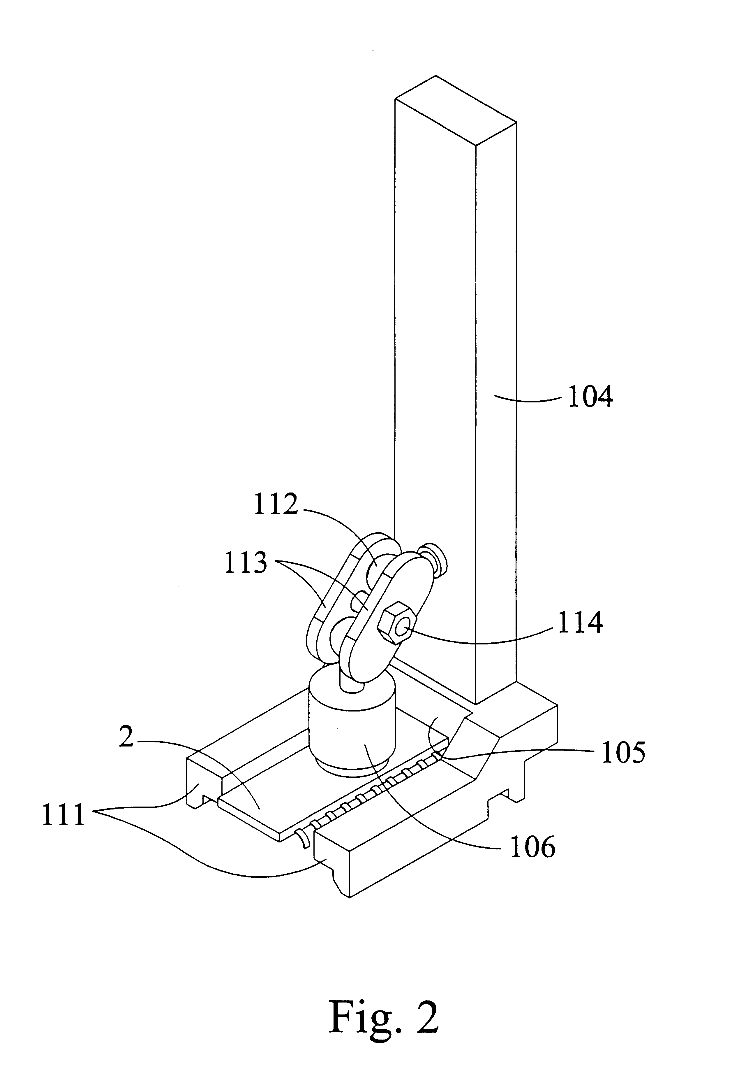
[0010]Another embodiment is an IC chip handling apparatus for removing an IC chip from a DUT board socket in a DUT board. This embodiment includes a body positionable in a first position and a second position and a depressor member coupled to the body. When the body is in the first position, the depressor member does not depress the DUT board socket and the IC chip is held in DUT board socket by clamping of the DUT board socket. When the body is in the second position the depre

Problems solved by technology

Accuracy is essential because mishandling can lead to misclassification, and consequently to re-testing of chips.
This practice is not optimal, however, because the small size and mass of IC chips can make the chips difficult to handle, and rough handling may lead to damage of the chips.
The manual devise, however, is prone to lose suction and release the IC chip prematurely.
A number of problems are associated with suction cups and vacuum lines.
For instance, suction cups and vacuum lines become inoperable when they are even partially severed or are punctured.
Suction cups may lose effectiveness as they age and become brittle.
Vacuum lines are more delicate and susceptible to turns and pinching than are electrical wires for instance.
Therefore, placing vacuum lines on the chip handling apparatus subjects the lines to damage.
A problem left unsolved by the prior art is to provide a device capable of operating functions of a conventional DUT board, as well as capable of handling an IC chip by more durable and less maintenance intensive means.

Method used


Image

  • Integrated circuit chip handling apparatus and method
  • Integrated circuit chip handling apparatus and method
  • Integrated circuit chip handling apparatus and method

Examples


transfer embodiment

[0035]In accordance with FIG. 3, an embodiment of the invention is for transferring an IC chip 2 between two locations. The embodiment includes a magnetic force source 6 for attaching to a face of the IC chip 2 when a current is applied to the magnetic force source 6. Additionally, the magnetic force source 6 is for releasing from the face of the IC chip 2 when the current is removed from the magnetic force source 6.

Transfer Mechanism

[0036]The present embodiment also includes a transfer mechanism 18 coupled to the magnetic force source 6. The transfer mechanism 18 is for moving the IC chip 2 between two locations. The transfer mechanism 18 includes a body 4, an actuator 8, and a transfer rail 19. The body 4 is essentially the same as the body 4 described in detail above. The actuator 8 is coupled to the body 4 for moving the body substantially perpendicularly toward and away from the face of the IC chip 3. For the purposes of description of the movement toward and away for the chip ...


PUM

PropertyMeasurementUnit
Forceaaaaaaaaaa
Currentaaaaaaaaaa
Gravityaaaaaaaaaa

Abstract

The present invention provides for an apparatus and method for handling integrated circuit (IC) chips such as thin small outline package (TSOP) IC chips. Embodiments of the invention are directed toward removal of TSOPs from device under test (DUT) boards. By use of magnetic forces generated by the invention, in combination with physical manipulation of the DUT boards and transfer structures, IC chips are quickly and efficiently transferred.

Description

TECHNICAL FIELD[0001]The present invention is directed toward an apparatus and method for handling integrated circuit chips through coordinated physical manipulation and application of magnetic forces. More specifically, embodiments of the invention are directed toward removal of thin small outline package (TSOP) integrated circuits (ICs) from device under test (DUT) board sockets.BACKGROUND OF THE INVENTION[0002]It is known in the art of handling IC chips such as TSOP chips to rely on the magnetic properties of a chip to exert forces on the chip. Such forces have been used to lift or align chips or to pull a chip to test the electrical connections of the chip to another component. The IC chip may have a magnetically chargeable material such as iron, nickel, or cobalt fabricated into a layer of the chip through which a magnetic force may be applied to the chip. Alternatively or in addition, the leads of the chip may be made of a magnetically chargeable material. In any case, magneti...

Claims


Application Information

Patent Timeline
IPC IPC(8): H05K3/00H05K13/02H05K13/04
CPCH05K13/021H05K13/0408Y10T29/53183Y10T29/53083Y10T29/49124Y10T29/49004H05K13/0409
Inventor FARRENS, OLIVERCASHIN, ROY
Owner MEI CALIFORNIA
Learn More