Dry cleaning machine

Active Publication Date: 2005-06-14
QINGDAO HAIER WASHING MASCH CO LTD +1
View PDF10 Cites 56 Cited by
  • Summary
  • Abstract
  • Description
  • Claims
  • Application Information

AI Technical Summary

Benefits of technology

[0029]In the processes of circulating drying step-exhausting drying step-cooling step, the drying cooler needs to be operated in the circulating drying step and in the cooling step. But, in the exhausting drying step between them, neither the drying cooler nor the solvent cooler needs to be operated. In the second dry cleaning machine, however, the refrigerator is operated even in the exhausting drying step, and either one of the drying cooler and the solvent cooler is continued its operation. Thus, the refrigerator never stops even when the exhausting drying step is short, so that it is assured that any off-time of the refrigerator is longer than a predetermined period. Since the refrigerator is continuously operated in the exhausting drying step, the on-time of the refrigerator can also be assured longer than a predetermined period even if the cooling step is short. These prevents o

Problems solved by technology

That is, only the cooler selected by the switch works, but the other cooler not selected by the switch does not work While the laundry i

Method used


Image

  • Dry cleaning machine
  • Dry cleaning machine
  • Dry cleaning machine

Examples


Embodiment Construction

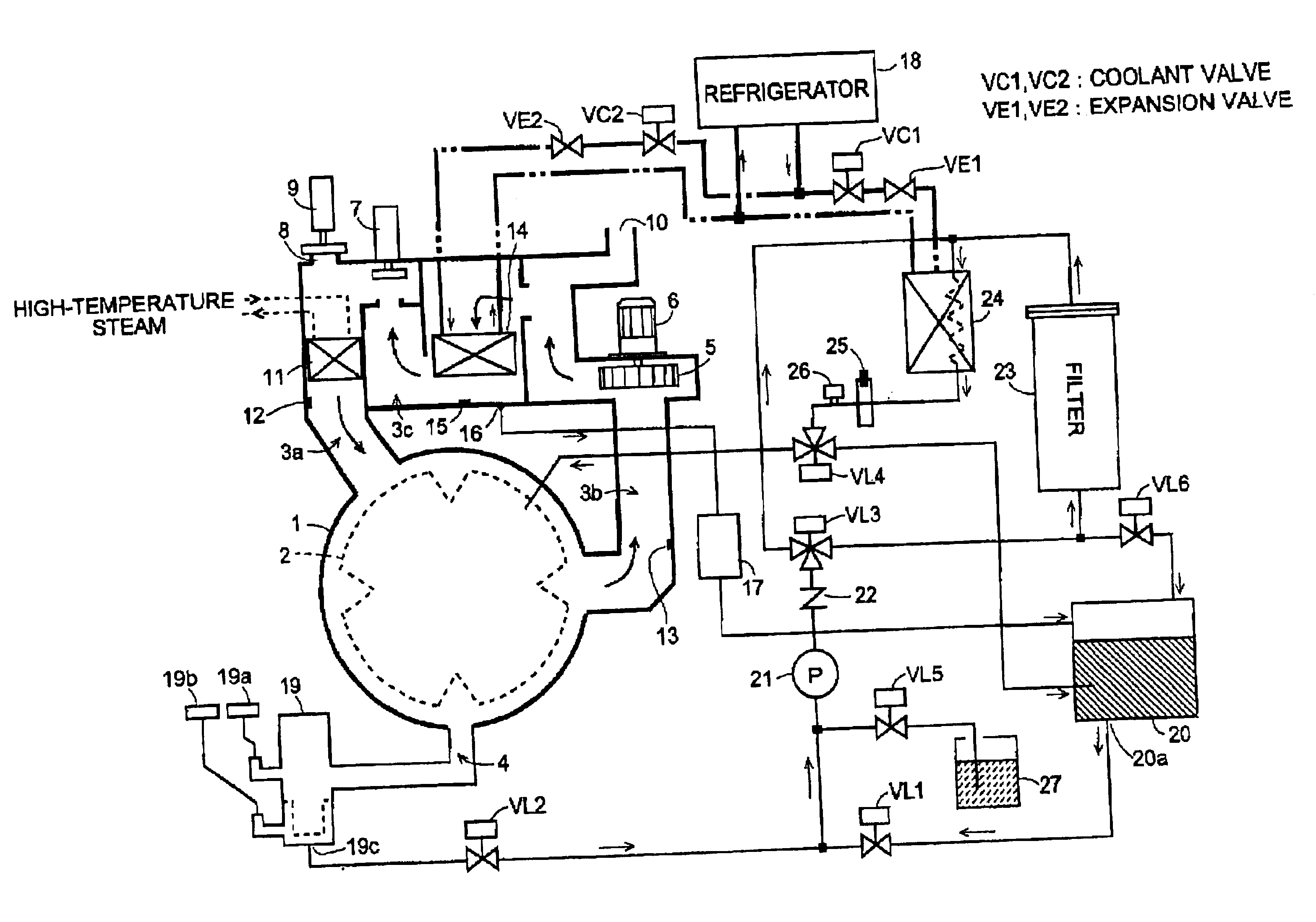
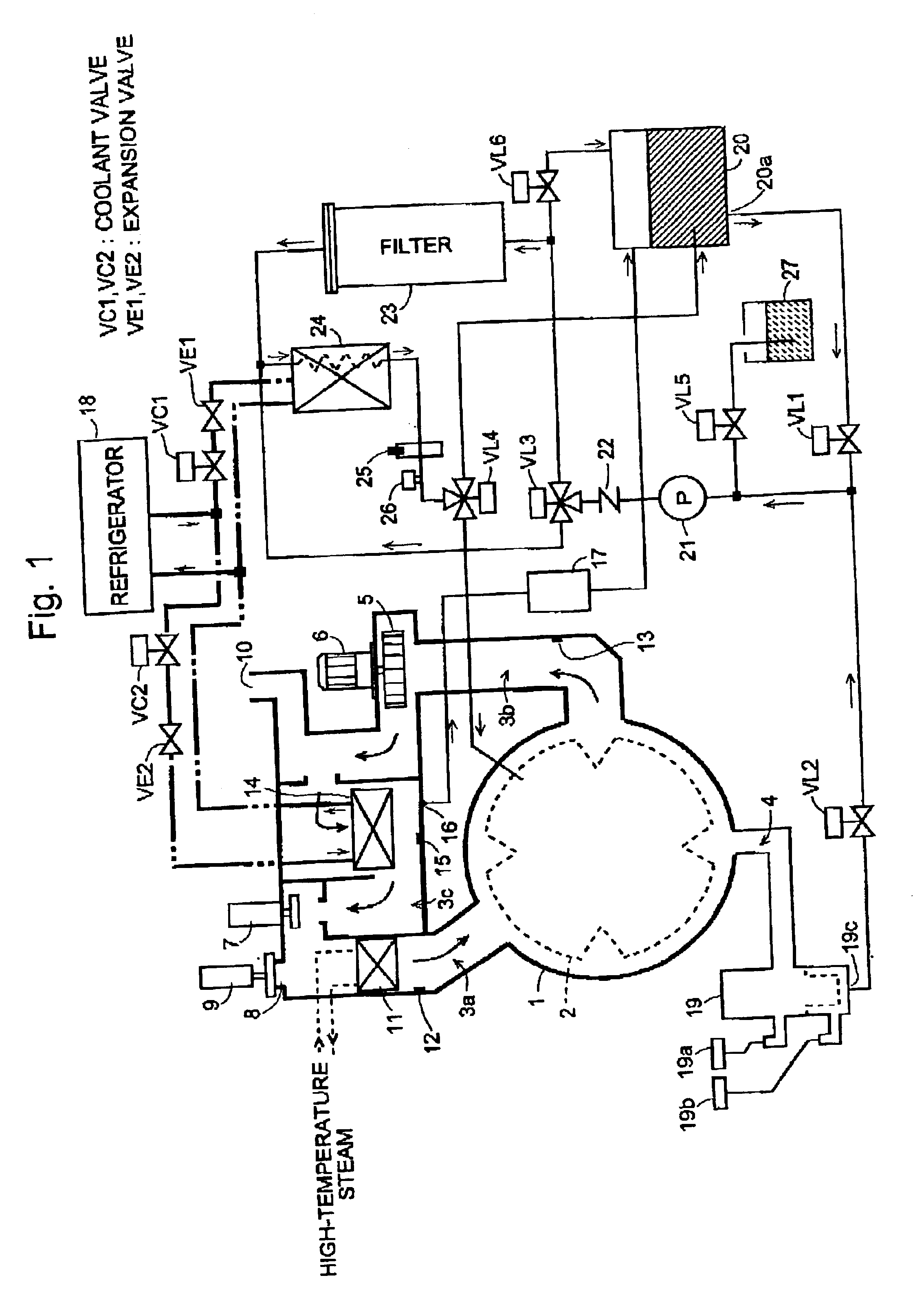
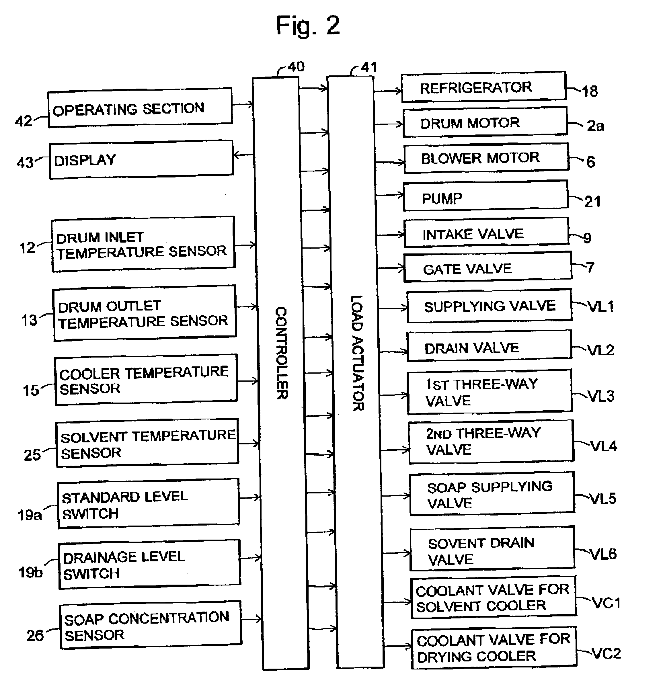
[0049]An embodiment of a drycleaner according to the present invention is described in reference to FIG. 1 to FIG. 6. In FIG. 1, there is shown a construction of relevant parts focusing on a piping diagram of this drycleaner. FIG. 2 illustrates its electric system. FIG. 3 is a flowchart illustrating cleaning process of the drycleaner. FIG. 4 is a table showing where coolant passages are connected to and purposes of refrigerator use in each step. FIG. 5 is a flowchart of the extracting step in its parts. FIG. 6 is a flowchart of an exhausting drying step in its main parts.

[0050]Referring first to FIG. 1, the structure of this drycleaner with a focus on its solvent flow is described.

[0051]In an outer tub 1, a cylindrical drum 2 having perforations is placed to rotate freely, and an intake path 3a, an exhaust path 3b and a solvent discharge pipe 4 are connected to the wall of the outer tub 1. The intake path 3a, the outer tub 1, the exhaust path 3b and an upper vent path 3c forms a ven...


PUM


Abstract

In the dry clearing machine, a common refrigerator is used for both the solvent cooler and the drying cooler, and the coolant compressed and liquefied in the refrigerator is supplied either one of the heat exchanger of the solvent cooler or that of the drying cooler, depending on the state of a switch. In the heat exchanger selected by the switch, the coolant is supplied and the solvent or the air is cooled when the coolant evaporates. That is, only the cooler selected by the switch works, but the other cooler not selected by the switch does not work. While the laundry is washed, normally, it is not necessary to supply air to the outer tub through the air path, and the drying cooler need not be operated. Thus, in the process of washing, the solvent is adequately cooled because an enough amount of coolant is supplied to the solvent cooler, and the temperature rise of the solvent is prevented.

Description

BACKGROUND OF THE INVENTION[0001]A known dry cleaning machine includes a solvent circulating path with the inlet at the bottom of the outer tub, which contains a rotating drum, and the outlet at the top of the outer tub. In the solvent circulating path, a pump and a filter are provided. In such a dry cleaning machine, the solvent is circulated through the circulating path by the pump and is cleaned by the filter while the laundry is washed Thus the solvent is not discharged from the dry cleaning machine and is repeatedly used.[0002]Petroleum solvent, for example, shows the best washing performance when it is around 25° C., and the washing efficiency decreases at higher or lower temperatures. Since the petroleum solvent has a rather low firing point, it bears safety problems when the temperature rises. In the above structure using the solvent circulating system, the temperature of the solvent changes due to the heat transfer from the surroundings, and the temperature rises due to the...

Claims


Application Information

Patent Timeline
IPC IPC(8): D06F43/08D06F43/00
CPCD06F43/086
Inventor NAGANAWA, MITSURUNISHINO, MASAFUMIKITAMURA, KEIJI
Owner QINGDAO HAIER WASHING MASCH CO LTD
Why Eureka
Try Eureka