
Compact inertial sensor

a sensor and inertial sensor technology, applied in the direction of acceleration measurement using interia force, instruments, devices using electric/magnetic means, etc., can solve the problems of complicated installation of the cell in the vehicle that it is to occupy, plate is more difficult to machine, etc., to achieve easy assembly, small stiffness, and easy to machine the effect of said elements

Inactive Publication Date: 2005-06-14
SAGEM DEFENSE SECURITE SA
View PDF6 Cites 8 Cited by
  • Summary
  • Abstract
  • Description
  • Claims
  • Application Information

AI Technical Summary

Benefits of technology

[0011]Thus, it is possible to obtain a structure that is compact, while nevertheless having a test mass that is sufficiently heavy.
[0013]This enables the size of the sensor to be further reduced.
[0015]Thus, it is possible to prevent the first mode of oscillation of the sensor as a whole disturbing measurements performed along the sensing axis of the sensor.
[0017]It is thus possible to make a plane sensor having a sensing axis which is contained in the plane of the sensor and whose position is affected little or not at all by manufacturing variation. In addition, with such a sensor, it is easy to arrange the link elements so that they present smaller stiffness along the sensing axis than in other directions. Specifically, the link elements work in bending for accelerations applied along the sensing axis, whereas the vibrating elements work in traction and compression, thus enabling the sensor to operate well, particularly at high frequency. Such a sensor is particularly simple to assemble. In addition, such a structure makes it possible to have link elements which extend over the entire thickness of the plate, thereby making it easier to machine said elements. Furthermore, sensor manufacture is made easier by the fact that the link elements can be made independently of the vibrating elements, thus making it possible, optionally, to make the link elements at some other time, or to do so in a plurality of operations.

Problems solved by technology

Nevertheless that makes the plate more difficult to machine.
In such cells, the extra thickness also leads to the sensing axis of the cell being inclined relative to a normal of the plate, thereby complicating installation of the cell in the vehicle that it is to occupy.

Method used


Image

  • Compact inertial sensor
  • Compact inertial sensor

Examples


first embodiment

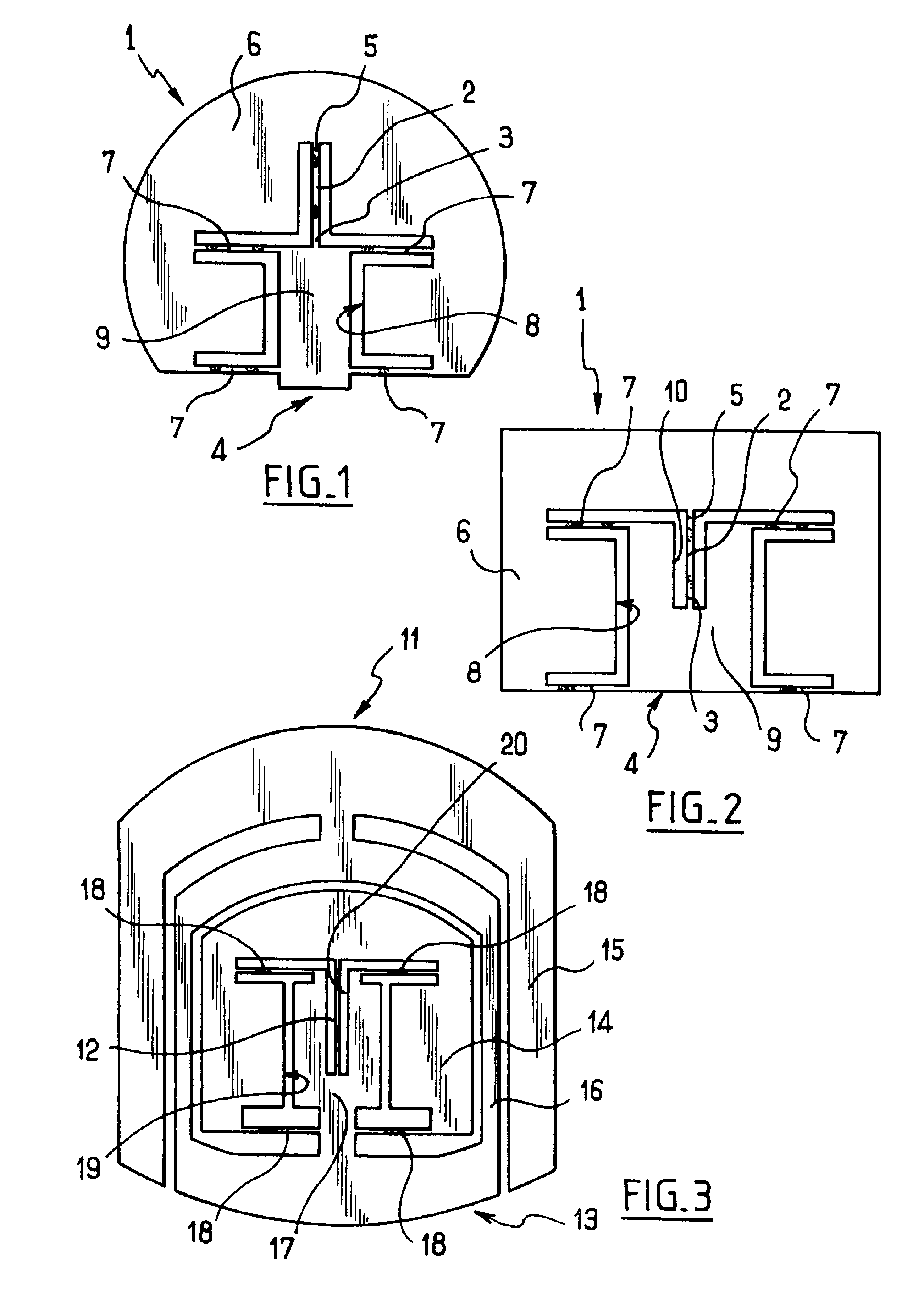
[0023]With reference to FIG. 1, the acceleration sensor constituting the first embodiment comprises a plate given overall reference 1 made of piezoelectric quartz crystal having defined therein in conventional manner a vibrating element 2 having an end 3 connected to a support element 4 designed to be fixed in a housing, and an opposite end 5 connected to a test mass 6.

[0024]The test mass 6 is hinged to the support element 4 via two pairs of link elements 7. In this case, the link elements 7 are formed by deformable tabs which are formed in the plate 1 and extend through the entire thickness of the plate 1. The link elements 7 are perpendicular to the vibrating elements 2 and the pairs of link elements 7 are disposed facing each other on either side of the support element 4. The link elements 7 are arranged to facilitate movement in translation of the test mass 6 relative to the support element in the plane of the plate 1. The sensing direction of the sensor is thus contained in sai...

second embodiment

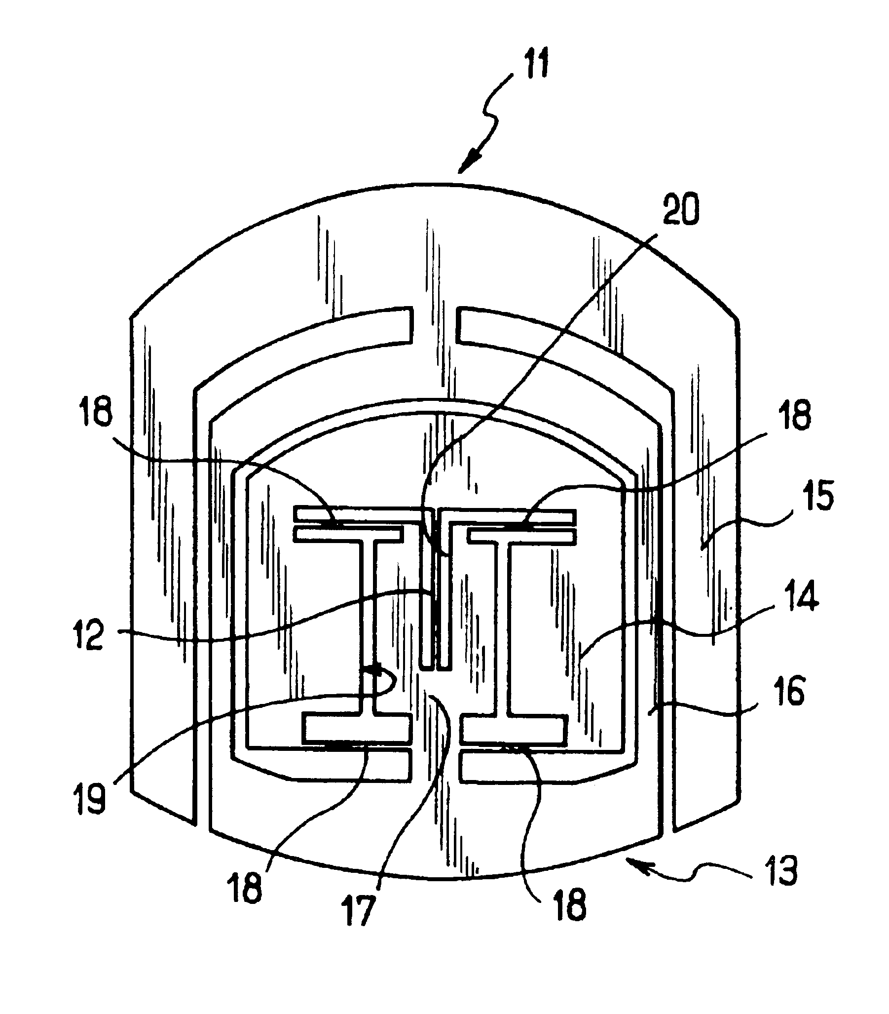
[0031]With reference to FIG. 3, the acceleration sensor constituting the second embodiment comprises a plate given overall reference 11 made of piezoelectric quartz crystal and having defined therein a vibrating element 12 with one end connected to a support element given overall reference 13 and an opposite end connected to a test mass 14. The support element 13 has a yoke-forming portion 15 for fixing in a housing, a decoupling frame 16 having one side secured to the yoke-forming portion 15 and an opposite side connected to a solid portion 17. The test mass 14 is connected to the solid portion 17 by the vibrating element 12 and link elements 18 which are constituted by deformable tabs formed in the plate 11 and which extend perpendicularly to the vibrating element 12. The link elements 18 are arranged to facilitate movement in translation of the test mass 14 relative to the support element 13 in such a manner that the sensing direction of the sensor is contained in the plane of th...


PUM


Abstract

The inertial sensor comprises at least one vibrating element having one end connected to a support element and an opposite end connected to a test mass which is hinged to the support element by at least two link elements and which includes a cavity in which the vibrating element and a portion of the support element adjacent to the vibrating element are received. The link elements are housed in the cavity surrounding a portion of the support element to which the link elements are connected.

Description

[0001]The present invention relates to inertial sensors, and in particular to accelerometers.[0002]More particularly, the invention relates to a sensor comprising a sensing cell comprising at least one vibrating element having one end connected to a support element and an opposite end connected to a test mass hinged to the support element via at least two link elements. The vibrating element is associated with excitation means which enable the vibrating element to be set into vibration and which enable the vibration frequency thereof to be detected.BACKGROUND OF THE INVENTION[0003]When a sensor of this type is subjected to acceleration, the test mass exerts a force on the vibrating element. This force changes the frequency of vibration in such a manner that the variation in the frequency of vibration of the vibrating element makes it possible to determine the acceleration to which the sensor is being subjected.[0004]It is advantageous to have cells of small size. This presents the a...

Claims


Application Information

Patent Timeline
Patent Type & Authority Patents(United States)
IPC IPC(8): G01P15/10G01P15/097G01P15/08G01P1/00
CPCG01P15/097G01P2015/0814
Inventor BAUDRY, HERVEFEATONBY, PAULLE ROY, JEAN-CLAUDE
Owner SAGEM DEFENSE SECURITE SA
Learn More