Convection steamer with forced recirculation through steam bath

Inactive Publication Date: 2005-06-14
MIDDLEBY MARSHALL
View PDF18 Cites 44 Cited by
  • Summary
  • Abstract
  • Description
  • Claims
  • Application Information

AI Technical Summary

Benefits of technology

[0003]A convection steam cooking device of the present invention utilizes forced recirculation of gases from the cooking cavity through a primary recirculation path that extends through a steam chamber. As the gases from the cooking cavity flow t

Problems solved by technology

For either arrangement, one problem is ensuring the proper distribution of steam within the cooking cavity for optimum cooking.
Such arrangements are believed to provi

Method used


Image

  • Convection steamer with forced recirculation through steam bath
  • Convection steamer with forced recirculation through steam bath
  • Convection steamer with forced recirculation through steam bath

Examples


Embodiment Construction

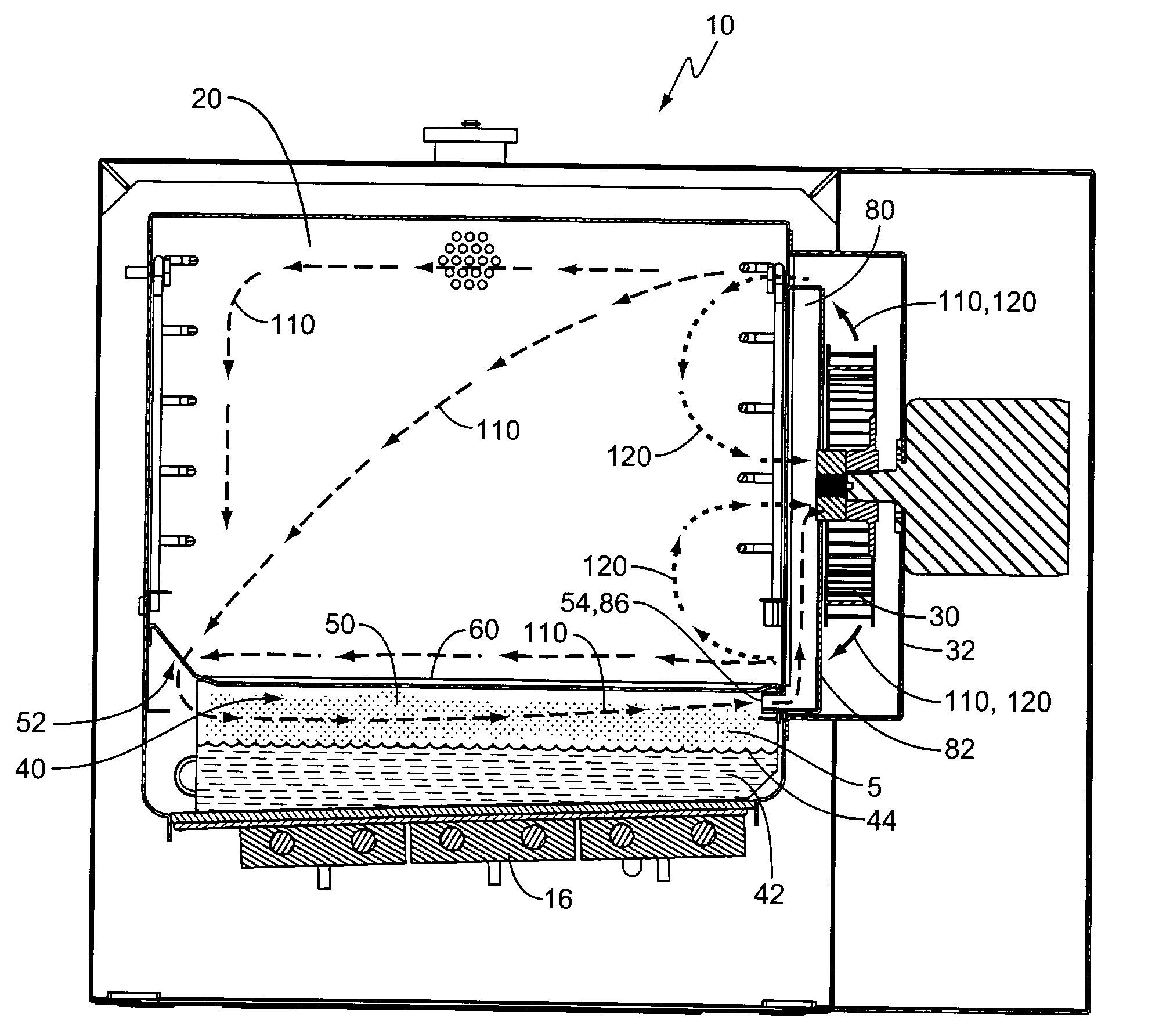
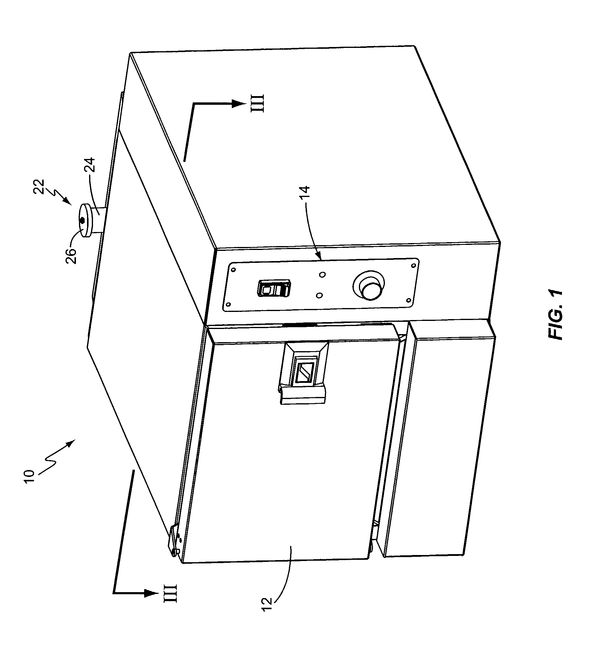
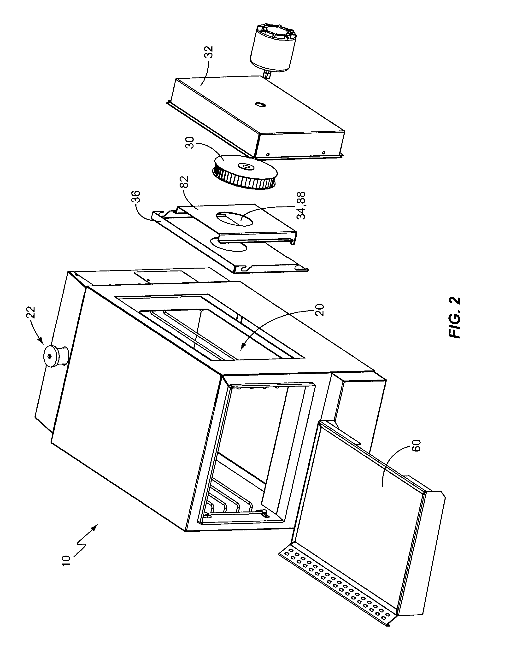
[0011]One embodiment of a cooking device according to the present invention, sometimes referred to herein as a convection steamer, or simply a steamer, is shown in FIGS. 1–2 and generally indicated at 10. From outward appearance, the steamer 10 may appear similar to steamers currently available on the market. Indeed, as is typical for such devices, the steamer 10 includes a latched door 12 for providing access to the cooking cavity 20 (see FIG. 2) and controls 14 to control the operation of the steamer 10. The controls 14 may take any form known in the art, and typically include an on / off switch, indicator lights, a timer and / or thermostat, and other suitable electronics. The electronics of the controls 14 may be segregated from cooking cavity 20 and may be advantageously vented to the ambient atmosphere for cooling. The cooking cavity 20 typically takes the form of a substantially rectangular chamber with racks for supporting food trays as is known in the art. In the present invent...


PUM


Abstract

A convection steam cooking device utilizes forced recirculation of gases along a primary recirculation path that extends through a steam chamber so that gases from the cooking cavity flow through the steam chamber and are subjected to a “steam bath” that alters the gases by adding heat and/or moisture. The cooking device includes a cooking cavity, a fan, a steam chamber disposed beneath the cooking cavity with a lower pool area for holding water and an upper steam collecting area disposed directly above the pool area, and a removable baffle disposed between the cooking cavity and the steam chamber with a perforated section remote from the fan and disposed at an upward angle. The primary forced recirculation path extends from the main cooking cavity, through the baffle, substantially across the steam collecting area, through a duct to the fan, and back to the main cavity.

Description

BACKGROUND OF THE INVENTION[0001]The present invention relates generally to the field of cooking devices, and specifically to commercial steam cooking devices.[0002]Modern steam ovens operate by heating water to generate steam and then supplying the steam to a cooking cavity containing food. Some of these steam ovens operate at low pressures, slightly above atmospheric, while others are openly vented to atmosphere. For either arrangement, one problem is ensuring the proper distribution of steam within the cooking cavity for optimum cooking. Some limited efforts have been made to use forced recirculation of the air / steam mixture in the cooking cavity, such as by using a recirculation fan connected to the cooking cavity, in order to make the cooking more efficient. The recirculation path for such units is typically simply from the cooking cavity directly to the fan and then back to the cooking cavity. Such units supply steam to the cooking cavity, typically by injecting steam directly...

Claims


Application Information

Patent Timeline
IPC IPC(8): A21B1/00A21B1/08A21B3/04F24C15/32
CPCF24C15/327A21B3/04
Inventor VROOM, ROBERT C.
Owner MIDDLEBY MARSHALL
Why Eureka
Try Eureka