Linerbolt removal tool

a technology of removal tool and liner, which is applied in the direction of portable percusive tools, boring/drilling equipment, drilling machines and methods, etc., can solve the problems of bolts becoming corroded, injury to workers, and difficult bolt removal at liner removal tim

a technology of removal tool and liner, which is applied in the direction of portable percusive tools, boring/drilling equipment, drilling machines and methods, etc., can solve the problems of bolts becoming corroded, injury to workers, and difficult bolt removal at liner removal tim

US6904980B2Inactive Publication Date: 2005-06-14RME HLDG

Image

  • Linerbolt removal tool
  • Linerbolt removal tool
  • Linerbolt removal tool

Examples


Embodiment Construction

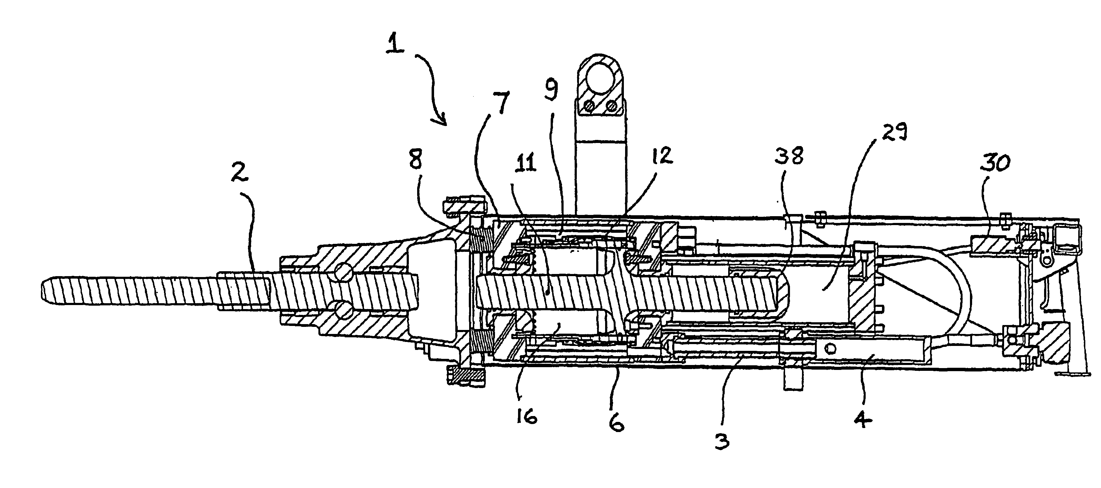
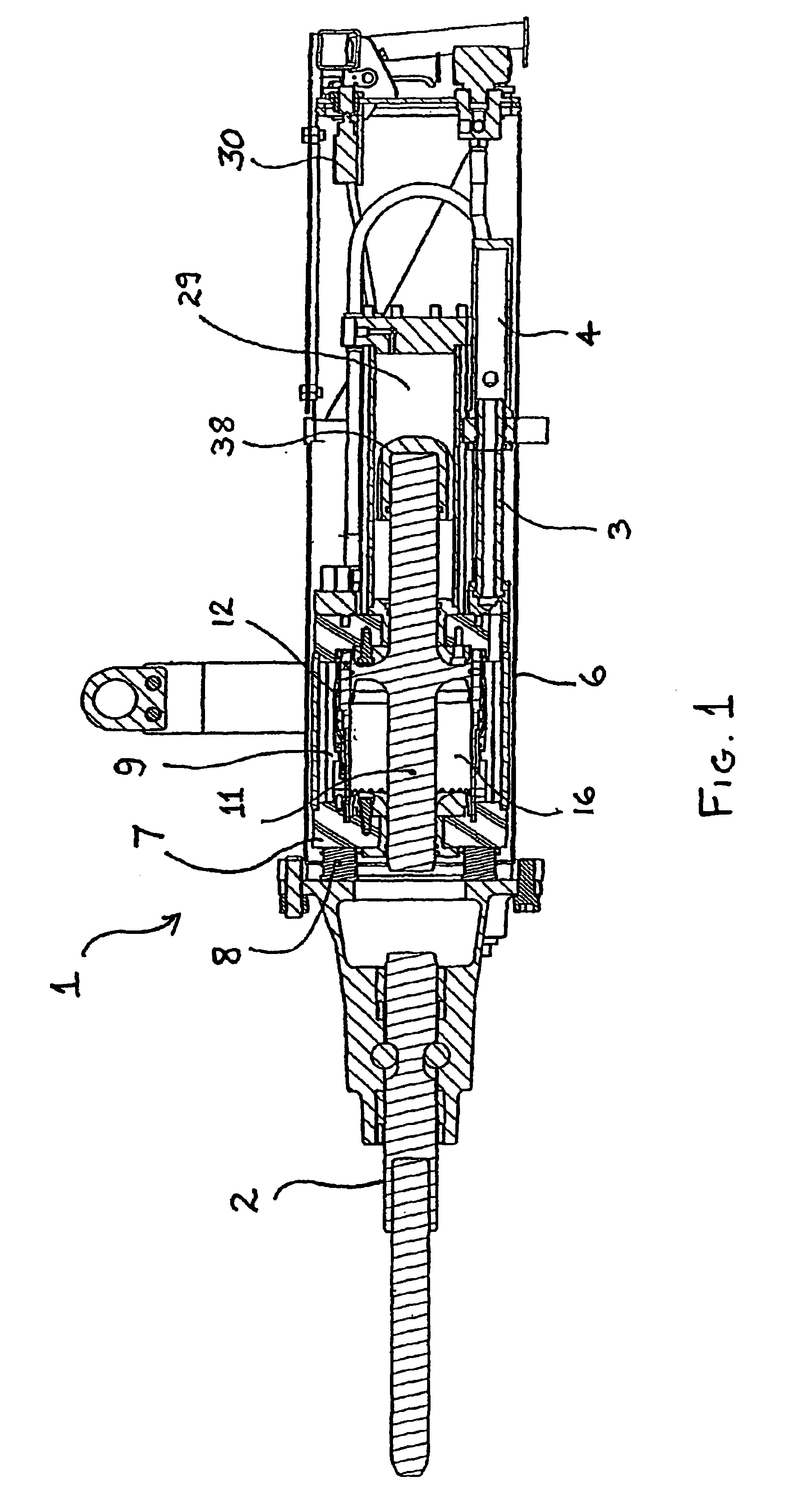
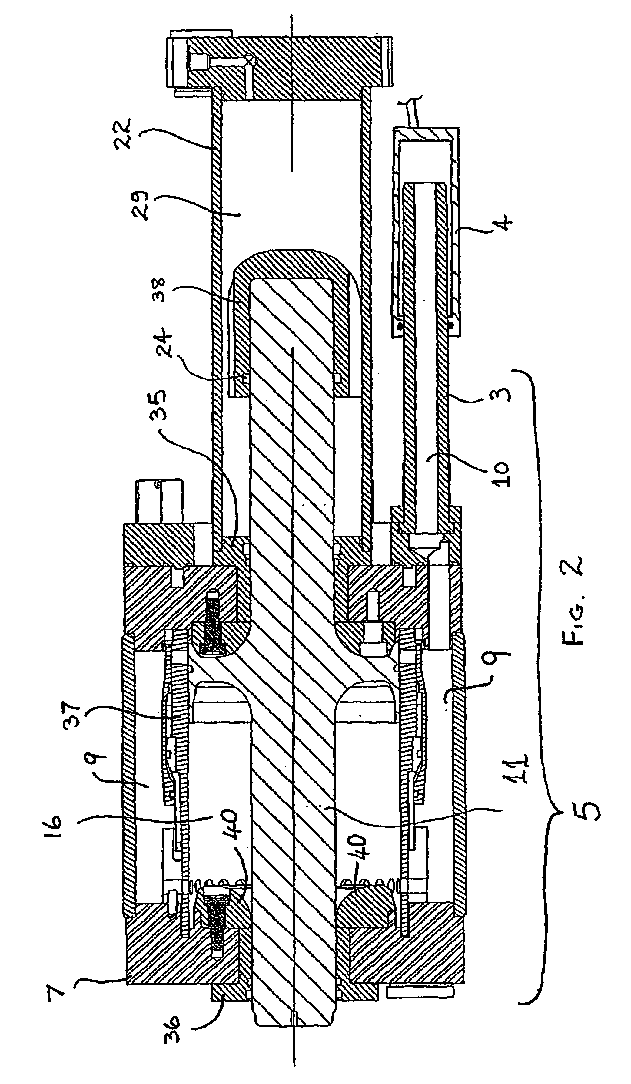
[0028]FIGS. 1 to 5 depicts a linerbolt removing tool 1 adapted to be suspended by a length adjustable sling (not shown) supported about its centre of gravity by a mounted overhead carriage (not shown), in a similar manner to the prior art tool disclosed in International Patent Publication No. WO97 / 26116. Tool 1, in a similar manner to the prior art tool, is readily pivoted about horizontal and vertical axes to align moil 2 with a bolt (not shown) to be removed from a mill casing (not shown).

[0029]An important feature of tool 1, is the operation of hollow tube 3 and cylinder 4 which actuate, hammer body 5. Air is supplied at relatively constant pressure and connected to a large reservoir. This ensures that the force at the end of hollow tube 3 is fairly constant. Cylinder 4 is anchored to the outer case 6, which the operator holds. This means that although large recoil forces are acting upon the hammer body 5 during the firing cycle, the effect on the operator is a constant low force...


PUM

PropertyMeasurementUnit
Pressureaaaaaaaaaa
Flexibilityaaaaaaaaaa
Distanceaaaaaaaaaa

Abstract

A pneumatic linerbolt removing tool including a moil supported for reciprocal movement along a hammer axis within a housing, an inertial body movably mounted along the hammer axis, and a piston assembly moveable within the inertial body along the hammer axis between a striking position at which it strikes the moil and a retracted position remote therefrom. The tool further including a gas-charged accumulator for urging the piston toward the moil and air supply to a cylinder adapted to urge a biasing piston on the inertial body relative to the housing and toward the moil. The inertial body being ported so that working air is supplied to a front face of the piston assembly to urge it to a coked position away from the moil and whereby the accumulator is in its compressed state, and selectively operable porting for equalizing pressure between the front and rear faces of the piston, to continuously allow transfer of air between the faces while in operation.

Description

TECHNICAL FIELD[0001]This invention relates to a linerbolt removing tool.BACKGROUND OF THE INVENTION[0002]A typical application of the present invention is in the removal of bolts from mining equipment, such as mills that utilise sacrificial segmented liners bolted to the internal casing of the mills which are regularly replaced during routine maintenance. Typically such mills may range in size from three meter to eleven meter in diameter and are lined with replaceable heavy steel segments attached internally to the mill casing by through bolting. In such applications the bolts become corroded and clearances between bolts and holes become compacted with ore fines. This results in difficult bolt removal at liner removal time. As a result the many bolts that are utilised to attach the liners to the mill shell: are often required to be freed manually by the use of large sledge-hammers. This is a difficult and time-consuming task that may result in injury to the workers.[0003]While it i...

Claims


Application Information

Patent Timeline
14 Jun 2005
Publication
US6904980B2
IPC
B25B27/04; B25B27/02; B23P19/06; B25D9/04; B25D9/20
CPC
B25B27/02; B25B27/04; B25B27/026
Inventors
RUBIE, PETER JOHN