Magnetic separator for linear dispersion and method for producing the same

a magnetic separator and linear dispersion technology, applied in the direction of particle separator tube details, separation processes, magnetic bodies, etc., can solve problems such as non-linear functions, and achieve the effects of reducing the total sector weight, minimizing the mass of the sector, and enhancing the efficiency of the magnetic circui

Inactive Publication Date: 2005-06-14
UNIV OF WASHINGTON +1
View PDF16 Cites 4 Cited by
  • Summary
  • Abstract
  • Description
  • Claims
  • Application Information

AI Technical Summary

Benefits of technology

[0013]The poles receive magnetic induction by either electrical, or by permanent fully polarized hard magnetic material such as ferrite or rare-earth permanent magnets (REPM). This creates a magnetic field between the poles. A flux return yoke consisting of highly permeable soft magnetic material may be present to enhance the efficiency of the magnetic circuit. The overall shape of the magnetic separator can either be rectilinear or curved to follow the curved charged particle trajectories and minimize the mass of the sector. Likewise, in order to reduce the total sector weight specific high energy product rare-earth permanent magnet (REPM) materials such as classes known as neodymiumiron-boron (NdFeB) or samarium-cobalt (SmCo) may be used. The pole and yoke material may be made from iron cobalt alloys commonly known as vanadium permendur and described in the ASTM Specification A801.

Problems solved by technology

The disadvantage of the uniform field magnetic sector is that the separation of adjacent particles with mE / q differing by fixed amounts is a non-linear function of position.

Method used


Image

  • Magnetic separator for linear dispersion and method for producing the same
  • Magnetic separator for linear dispersion and method for producing the same
  • Magnetic separator for linear dispersion and method for producing the same

Examples


Embodiment Construction

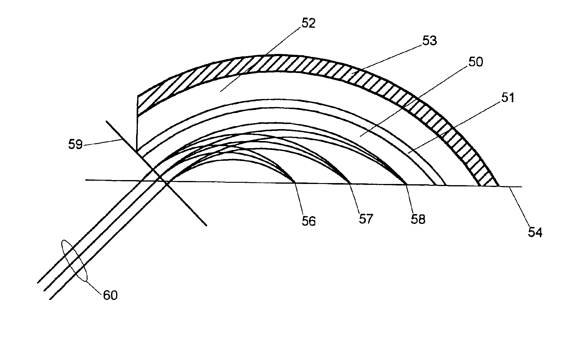
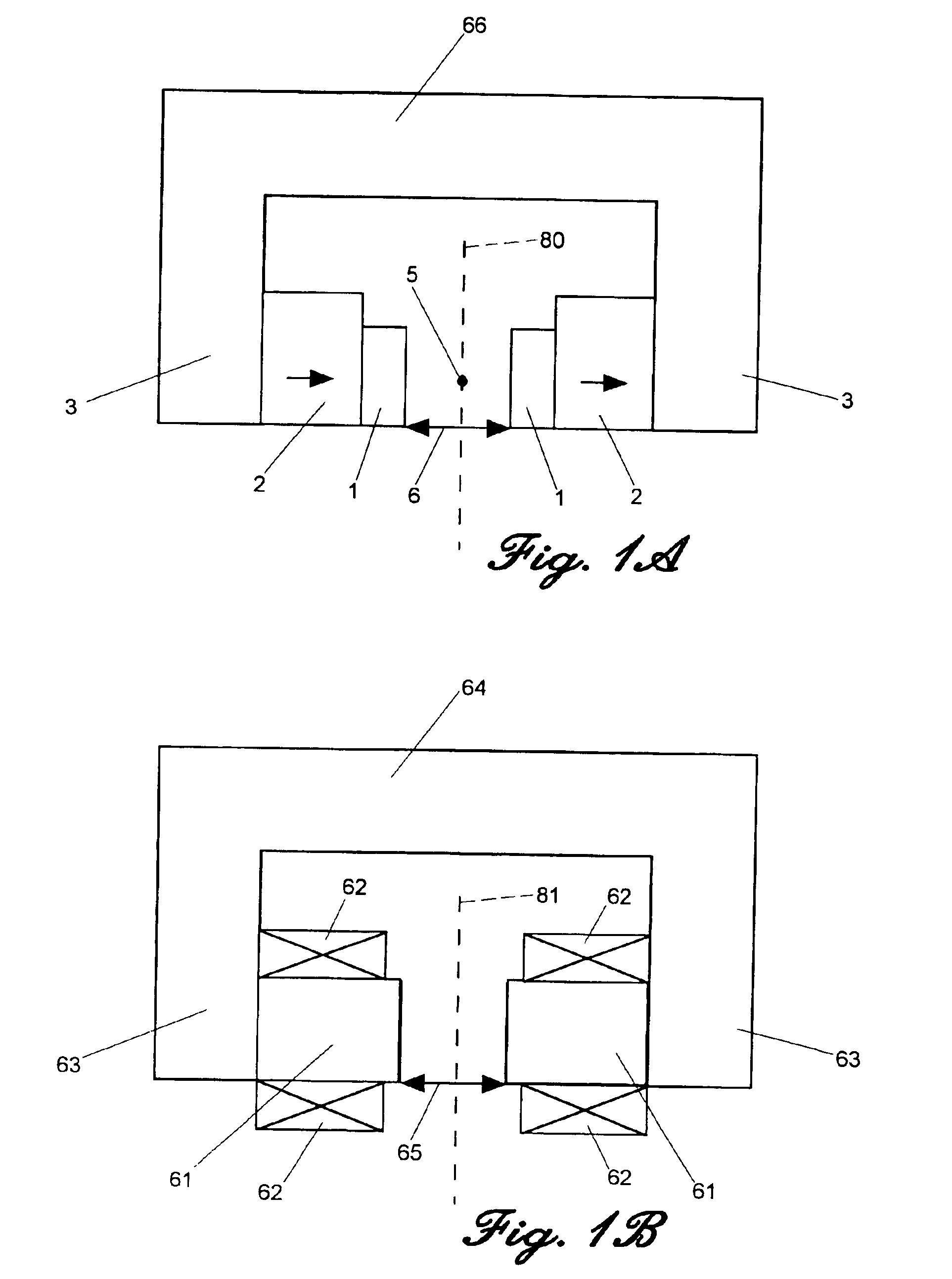
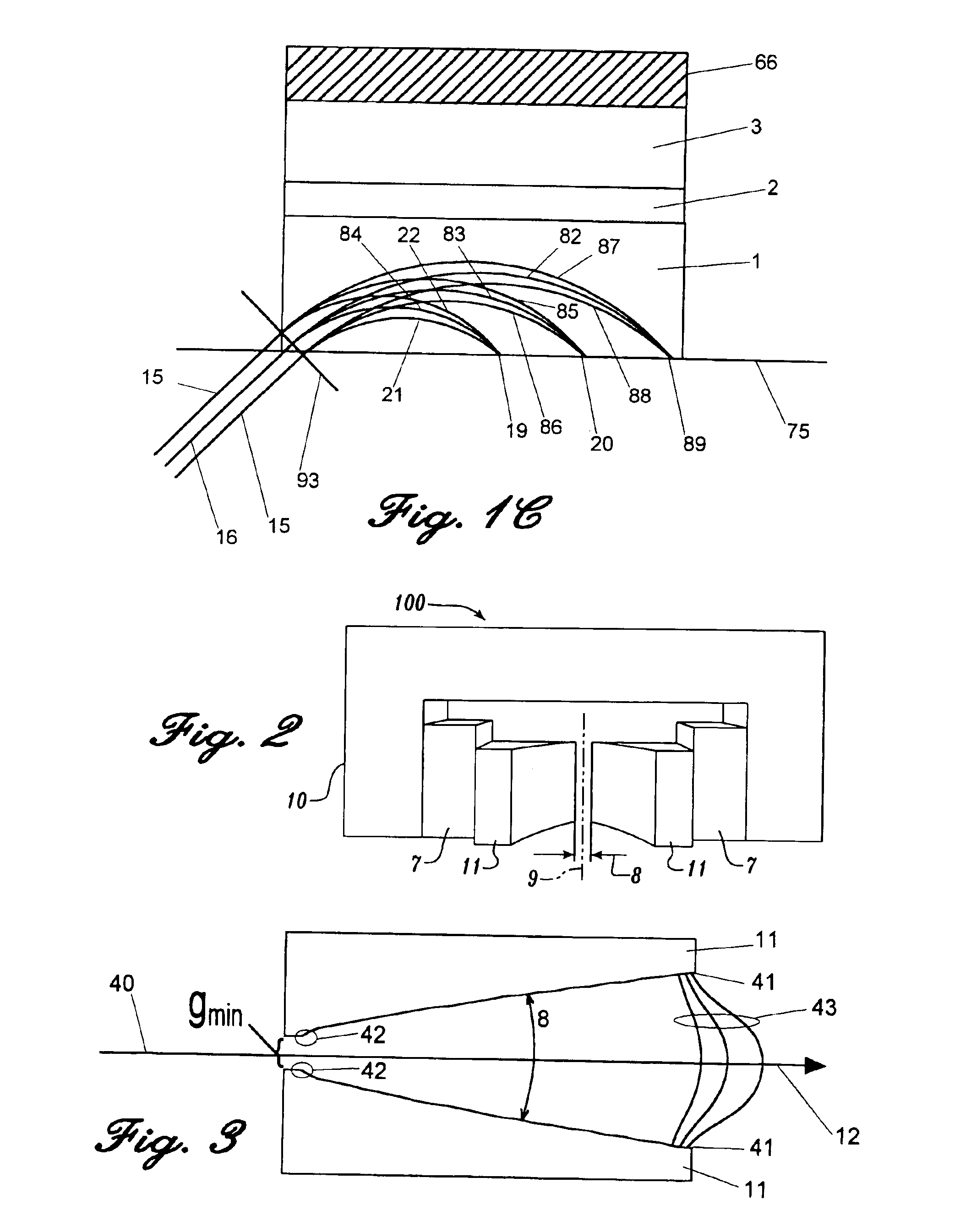
[0041]FIG. 1A is a schematic diagram of a permanent magnet separator with a uniform field in two planes known in the prior art which results in a square-root mass-energy-to-charge ratio dispersion of charged particles. It consists of two high magnetically permeable parallel poles 1 made from suitable iron alloy such as vanadium permendur with magnets 2 made from a suitable ferrite or rare-earth permanent magnet (REPM) such as neodymium iron boron. A high magnetically permeable yoke 3 completes the magnetic circuit by connecting the magnets 2. The gap 6 between the poles is carefully held parallel and symmetric about a center axis 80 in a plane transverse to the axis 5 and along the axis 5. The number and disposition of the permanent magnets 2 within the magnetic circuit is varied and they may be located anywhere within the magnetic flux path 3 and may even be incorporated into the back portion of the return yoke 66. The magnetic return yoke 3 and back yoke 66 are not required, but g...


PUM


Abstract

A magnetic sector for charged particle beam transport that includes a magnetic field profile that achieves a linear dispersion from a collimated beam of charged particles proportional to their mass-energy-to-charge ratio. In one embodiment, the field profile necessary for the linear dispersion is obtained by the use of shaped, highly permeable poles powered by permanent magnets or electromagnetic coils.

Description

CROSS-REFERENCES TO RELATED APPLICATIONS[0001]This application is a divisional of U.S. patent application Ser. No. 10 / 052,891, filed Jan. 18, 2002, now U.S. Pat. No. 6,843,375 which is a continuation of U.S. patent application Ser. No. 09 / 469,662, filed Dec. 22, 1999, now abandoned which is a divisional of U.S. patent application Ser. No. 09 / 325,936, filed Jun. 4, 1999, now U.S. Pat. No. 6,182,831, issued Feb. 6, 2001, which is a continuation of International Application No. PCT / US98 / 21000, filed Oct. 6, 1998, which claims the benefit of U.S. Provisional Patent Application No. 60 / 061,394, filed Oct. 7, 1997, priority of the filing dates of which is hereby claimed under 35 U.S.C. §§ 120 and 119, respectively. Each of these applications is incorporated hereby by reference.FIELD OF THE INVENTION[0002]This invention relates to applications of charged particles transport where a dispersion of the particles is desired by either a function of mass, energy or charge. More particularly, the ...

Claims


Application Information

Patent Timeline
Patent Type & Authority Patents(United States)
IPC IPC(8): H01J49/02H01J49/26H01J49/30
CPCH01J49/30H01J49/025
Inventor SCHEIDEMANN, ADI A.ROBINSON, KEMJONES, PATRICK L.GOTTSCHALK, STEPHEN C.
Owner UNIV OF WASHINGTON
Why Eureka
Try Eureka