Magnetron

A magnetron and magnetic ring technology, applied in the field of magnetrons, can solve problems such as reducing the efficiency of the magnetic circuit, and achieve the effects of stable magnetic field distribution and improved magnetic circuit efficiency

Active Publication Date: 2013-02-13
PANASONIC CORP
View PDF1 Cites 0 Cited by
  • Summary
  • Abstract
  • Description
  • Claims
  • Application Information

AI Technical Summary

Problems solved by technology

This creates the problem that the cuts or protrusions block the flow of magnetic flux lines, thereby reducing the efficiency of the magnetic circuit

Method used


Image

  • Magnetron
  • Magnetron
  • Magnetron

Examples


Embodiment Construction

[0046] Hereinafter, preferred embodiments of the present invention will be explained in detail with reference to the accompanying drawings.

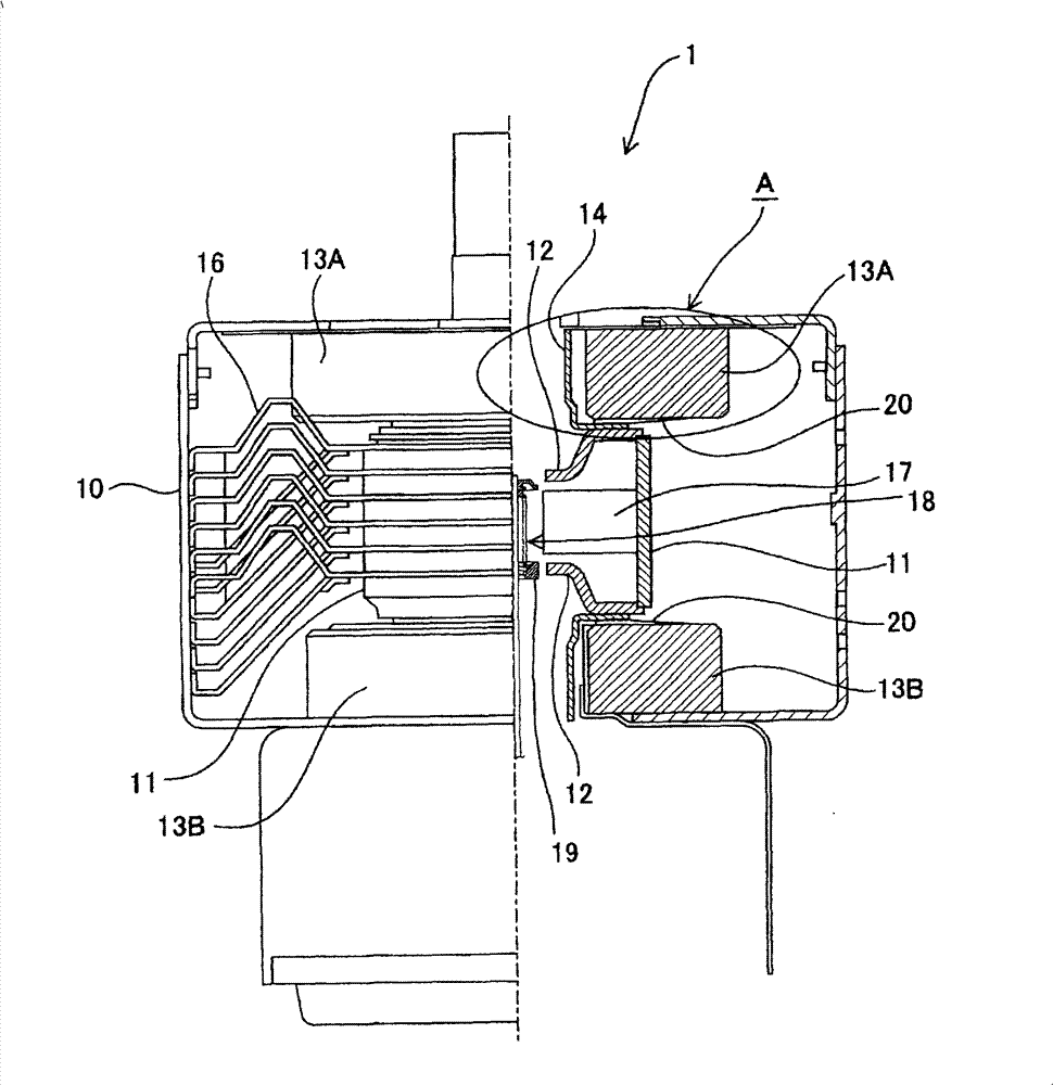
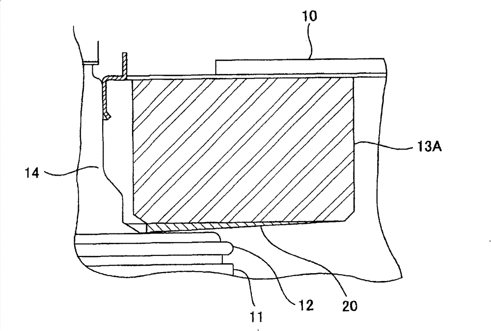
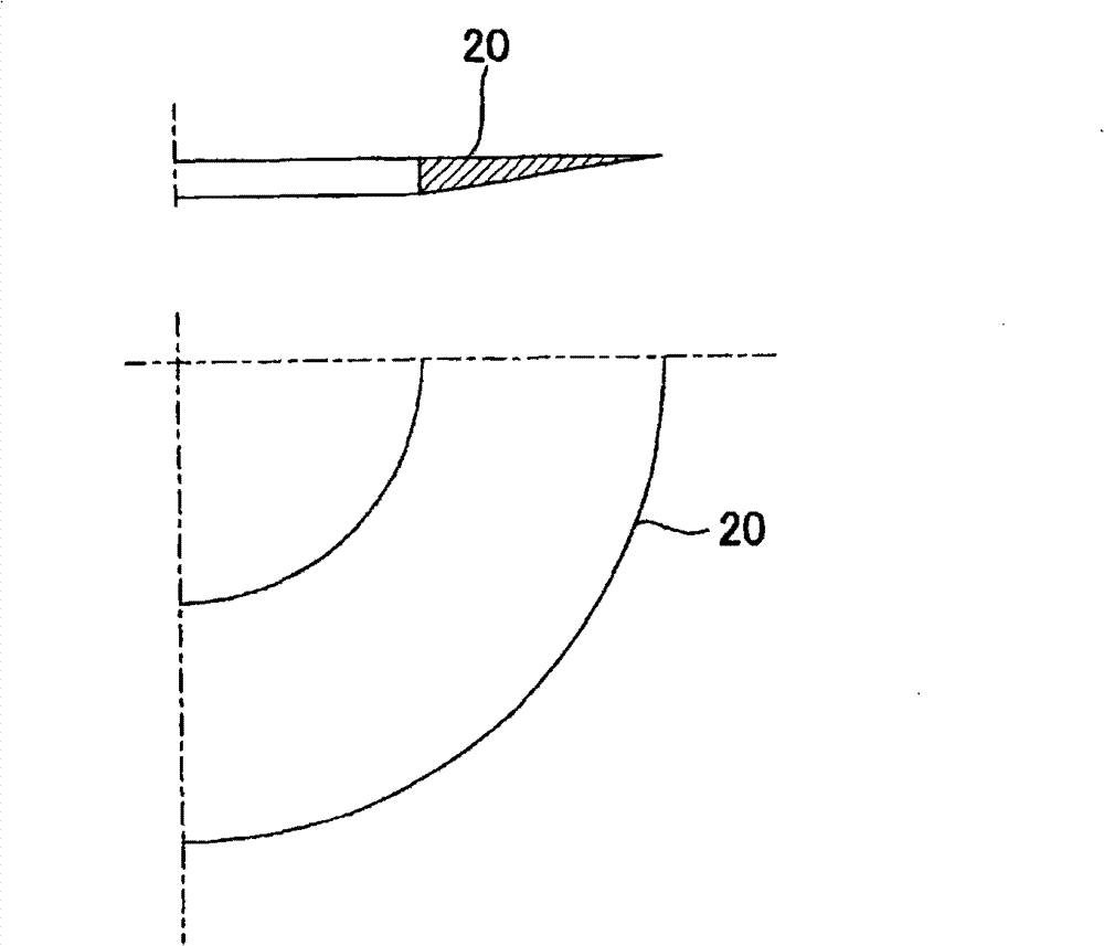
[0047] figure 1 is a partial cross-sectional view of a magnetron according to an embodiment of the present invention, and shows the anode barrel, ring magnet, cooling fins, etc. within the yoke. figure 2 yes figure 1 Enlarged view of part A of the magnetron 1 shown. exist figure 1 with 2In the yoke 10, there are arranged in the yoke 10: an anode cylinder 11, and magnetic pole pieces 12 are respectively fixed at the opening ends on both sides thereof; ring magnets 13A, 13B in the shape of donuts are respectively arranged on the upper part of the anode cylinder 11 and immediately below the lower part. below; and side pipe 14, on the anode side. Further, magnet rings 20 are arranged between a part of the upper part of the side pipe 14 and the ring magnet 13A and between a part of the lower part of the side pipe 14 and the ring magn...


PUM


Abstract

The present invention provides a magnetron which can conduct more magnetic flux in the active space at the periphery of a cathode structure to thereby further improve the efficiency of a magnetic circuit. The magnetron of the present invention includes an anode cylinder on which inner wall a plurality of anode vanes are provided, a pole piece provided on an end side of the anode cylinder, a circular magnet provided on the vicinity of the pole piece, and a magnet ring provided between the anode cylinder and the circular magnet. An outer diameter of the magnet ring is smaller than or equal to the outer diameter of the circular magnet and larger than or equal to the outer diameter of the anode cylinder. The magnet ring has a portion on a surface of the pole piece side whose normal line is non-parallel to the central axis of the anode cylinder.

Description

technical field [0001] The present invention relates to a magnetron used in a microwave utilizing device such as a microwave oven. Background technique [0002] The aforementioned magnetron is configured, for example, in such a way that a magnetic ring formed of magnetic material (also referred to as a transfer plate or backing plate) is arranged between the anode cylinder and the ring magnet to increase the magnetic force in the active space around the cathode structure, which The anode cylinder has anode vanes arranged radially on the inner wall surface thereof, and the ring magnet is arranged on the open end side of the anode cylinder (for example, see JP-A-2002-163993). Due to the arrangement of the magnetic ring, a large amount of magnetic flux can be conducted into the action space, so that the efficiency of the magnetic circuit can be increased. [0003] In order to increase the efficiency of the magnetic circuit, it is important to conduct a large amount of magnetic...

Claims


Application Information

Patent Timeline
Patent Type & Authority Patents(China)
IPC IPC(8): H01J25/50H01J23/02H05B6/64
Inventor 熊仓绫子桑原渚齐藤悦扶
Owner PANASONIC CORP
Why Eureka
Try Eureka