An ultra-thin speaker and its portable audio

A loudspeaker, ultra-thin technology, applied in the directions of loudspeakers, sensors, electrical components, etc., can solve the problems of loudspeaker distortion, loudspeaker occupying a large space, and high loudspeaker height, reducing the thickness of the loudspeaker, improving the efficiency of the magnetic circuit, and improving the sound quality. Effect

Active Publication Date: 2022-05-20
SHENZHEN DEHUIDA INTELLIGENT TECH CO LTD
View PDF12 Cites 0 Cited by
  • Summary
  • Abstract
  • Description
  • Claims
  • Application Information

AI Technical Summary

Problems solved by technology

The structure of traditional speakers is generally as follows figure 1 As shown, it includes the pot frame 1 extending obliquely upward, the terminal board 2 is installed on the ribs on the lower surface of the pot frame 1, the T iron 11 is installed on the bottom of the pot frame 1, and the T iron 11 is provided with a magnet 3. 4 is bonded to the upper surface of the magnet 3, and the elastic wave 5 is installed inside the basin frame 1, and the middle hole of the elastic wave 5 is provided with a voice coil 6, and the lower part of the voice coil 6 is located between the T iron 11 and the washer, and the vibration The middle hole of the diaphragm 7 is connected to the top of the voice coil 6, the outer ring of the diaphragm 7 is connected to the sound outlet of the basin frame 1, a ring is provided at the sound outlet of the basin frame 1, and the upper end of the voice coil 6 is provided with glue. The dustproof cap 10 of knot, the loudspeaker designed with this structure has the following disadvantages: 1. The diaphragm becomes a horn-shaped, which makes the height of the whole loudspeaker higher and takes up a lot of space; 2. The elastic wave is connected with the voice coil, causing the elastic wave It should be separated from the diaphragm by a certain distance to prevent the sound quality of the speaker from being affected when the diaphragm is touched. From another angle, the entire speaker will take up a large space; 3. All parts are connected by glue, and the manufacturing process is complicated. , the glue is easy to fall off after being subjected to vibration, resulting in speaker distortion

Method used


Image

  • An ultra-thin speaker and its portable audio
  • An ultra-thin speaker and its portable audio

Examples


Embodiment Construction

[0019] The technical solutions of the present invention will be further described below in conjunction with the accompanying drawings and through specific implementation methods.

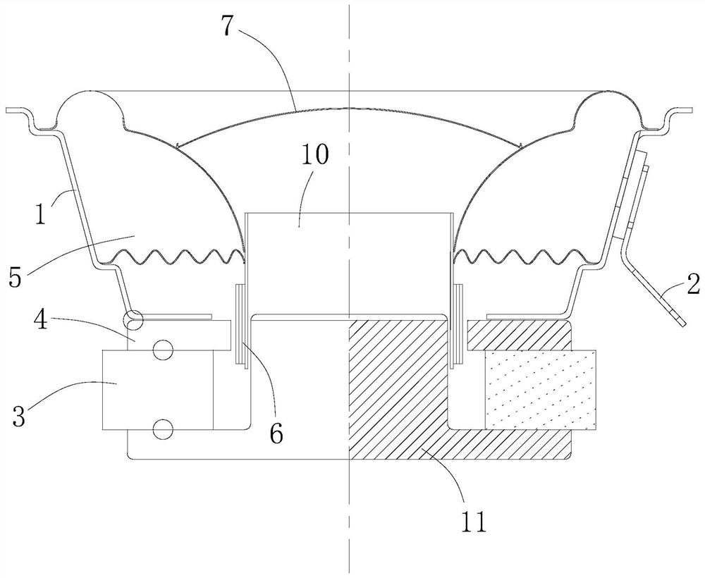
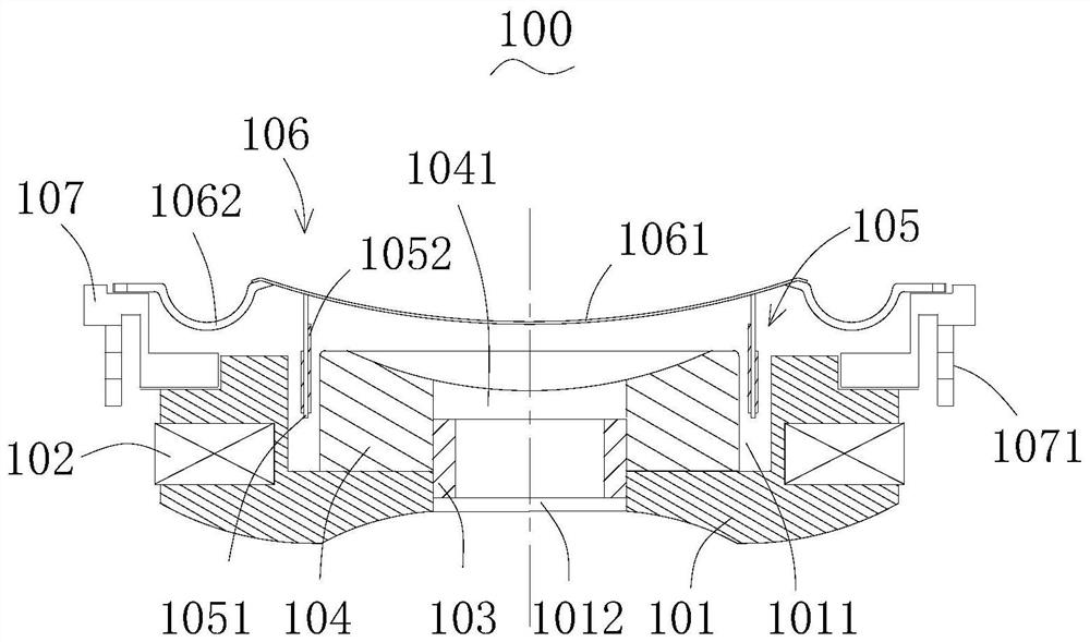
[0020] combine figure 1 and figure 2 As shown, an ultra-thin horn in this embodiment includes a magnetic circuit device and a vibrating device matched with the magnetic circuit device. The magnetic circuit device includes a T iron 101, and a The outer magnetic ring 102 matched with the groove on the circumferential surface, the inner magnetic ring 103 matched with the pit 1011 in the middle of the T iron 101, and the washer 104 matched with the inner magnetic ring 103; There is a gap between the Saihuasi 104 and the inner side wall of the pit 1011; the vibration device includes a diaphragm 106, and a bracket 107 matched with the periphery of the diaphragm 106, and the voice coil 105 is fastened On the lower bottom surface of the diaphragm 106, and the voice coil 105 is inserted in the gap between...


PUM


Abstract

The invention discloses an ultra-thin speaker and its portable audio system, comprising a magnetic circuit device and a vibrating device matched with the magnetic circuit device. The outer magnetic ring matched with the groove on the circumferential surface, the inner magnetic ring matched with the pit in the middle of the T iron, and the washer matched with the inner magnetic ring; the washer and the A gap is provided between the inner side walls of the pits, and the voice coil of the vibrating device is inserted into the gap. With this structural design, compared with traditional speakers, the thickness of the speaker can be effectively reduced, the efficiency of the magnetic circuit can be improved, and the sound quality of the speaker can be improved.

Description

technical field [0001] The invention relates to the technical field of loudspeakers, in particular to an ultra-thin loudspeaker and a portable audio system thereof. Background technique [0002] The horn, also known as the loudspeaker, is an electroacoustic transducer that converts electrical energy into sound energy through a certain physical effect. When different electronic energies are transmitted to the voice coil of the speaker, the voice coil generates an energy that interacts with the magnetic field of the magnet. This interaction causes the diaphragm to vibrate. Because the electronic energy changes at any time, the voice coil of the speaker will move forward or backward , so the horn's diaphragm will move accordingly, and this action changes the density of the air to produce sound. [0003] As LED technology is applied to video fields such as televisions, monitors, and notebook computers, video equipment continues to pursue thinner thickness, and the image quality...

Claims


Application Information

Patent Timeline
Patent Type & Authority Patents(China)
IPC IPC(8): H04R9/06H04R9/02
CPCH04R9/02H04R9/06H04R2400/11
Inventor 唐文亮
Owner SHENZHEN DEHUIDA INTELLIGENT TECH CO LTD
Why Eureka
Try Eureka