LCD with diffuser having particular haze value and diffuser-reflector distance, and reduced parallax

a liquid crystal display and diffuser technology, applied in non-linear optics, identification means, instruments, etc., can solve the problems of increased power consumption, reduced light quantity, and difficult to see display

Inactive Publication Date: 2005-06-14
BOE TECH GRP CO LTD
View PDF33 Cites 29 Cited by
  • Summary
  • Abstract
  • Description
  • Claims
  • Application Information

AI Technical Summary

Benefits of technology

[0041]With the electronic apparatus of the present invention, it is possible to realize an electronic apparatus which is free from parallax or color mixing.

Problems solved by technology

In the case of a reflection type display device, the quantity of light is reduced in a dark place, so that the display is hard to see.
In the case of a transmission type display device, the power consumption increases in proportion to the light source regardless of whether the place is light or dark, so that it is not particularly suitable for a portable display device or the like operated by a battery.
While in the above-described prior art only a transflective display device has been shown, such problems are equally involved in a reflection type display device formed by removing the light source 5210 from the display device of FIG.
Thus, the light emitted from the light source 5210 cannot be effectively utilized to a sufficient degree, with the result that the display is rather dark.

Method used


Image

  • LCD with diffuser having particular haze value and diffuser-reflector distance, and reduced parallax
  • LCD with diffuser having particular haze value and diffuser-reflector distance, and reduced parallax
  • LCD with diffuser having particular haze value and diffuser-reflector distance, and reduced parallax

Examples


first embodiment

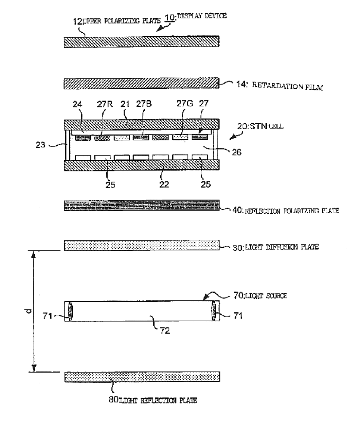
[0094]FIG. 5 is a schematic diagram showing a color display device 10 according to a The display device 10 uses an STN cell 20 as transmission polarization axis variable means. Further, above the STN cell 20, a retardation film 14 and an upper polarizing plate 12 are sequentially provided, and below the STN cell 20, a light diffusion plate 30 and a lower polarizing plate 15 are sequentially provided. Further, below the lower polarizing plate 15, a reflection polarizing plate 40, a light source 70 and a light reflection plate 80 are sequentially provided.

[0095]Here, the light source 70 uses an LED (light emitting diode) 71, emitting light upwardly by a light guiding member 72. The light guiding member 72 is formed of a transparent resin such as acrylic resin, polycarbonate resin or amorphous polyolefine, an inorganic transparent material such as glass, or a composite thereof, and has a thickness of approximately 0.3 mm to 2 mm. Further, a plurality of small protrusions are formed on...

second embodiment

[0111]FIG. 6 is a schematic diagram showing a display device for black and white display according to a That is, in the display device 10, instead of the STN cell 20 having the color filter 27, an STN cell 20′ not equipped with a color filter 27 is used. Further, below the STN cell 20′, the lower polarizing plate 15, the light diffusion plate 30, the reflection polarizing plate 40, the light source 70 and the light reflection plate 80 are sequentially provided.

[0112]In this display device 10 of the second embodiment also, constructed as described above, light is sequentially reflected between the reflection polarizing plate 40 and the light reflection plate 80, as in the display device 10 of the first embodiment, causing only light having a linear polarization component in a predetermined direction to be applied from the reflection polarizing plate 40 to the STN cell 20′, whereby it is possible to make the screen bright in reflection type display.

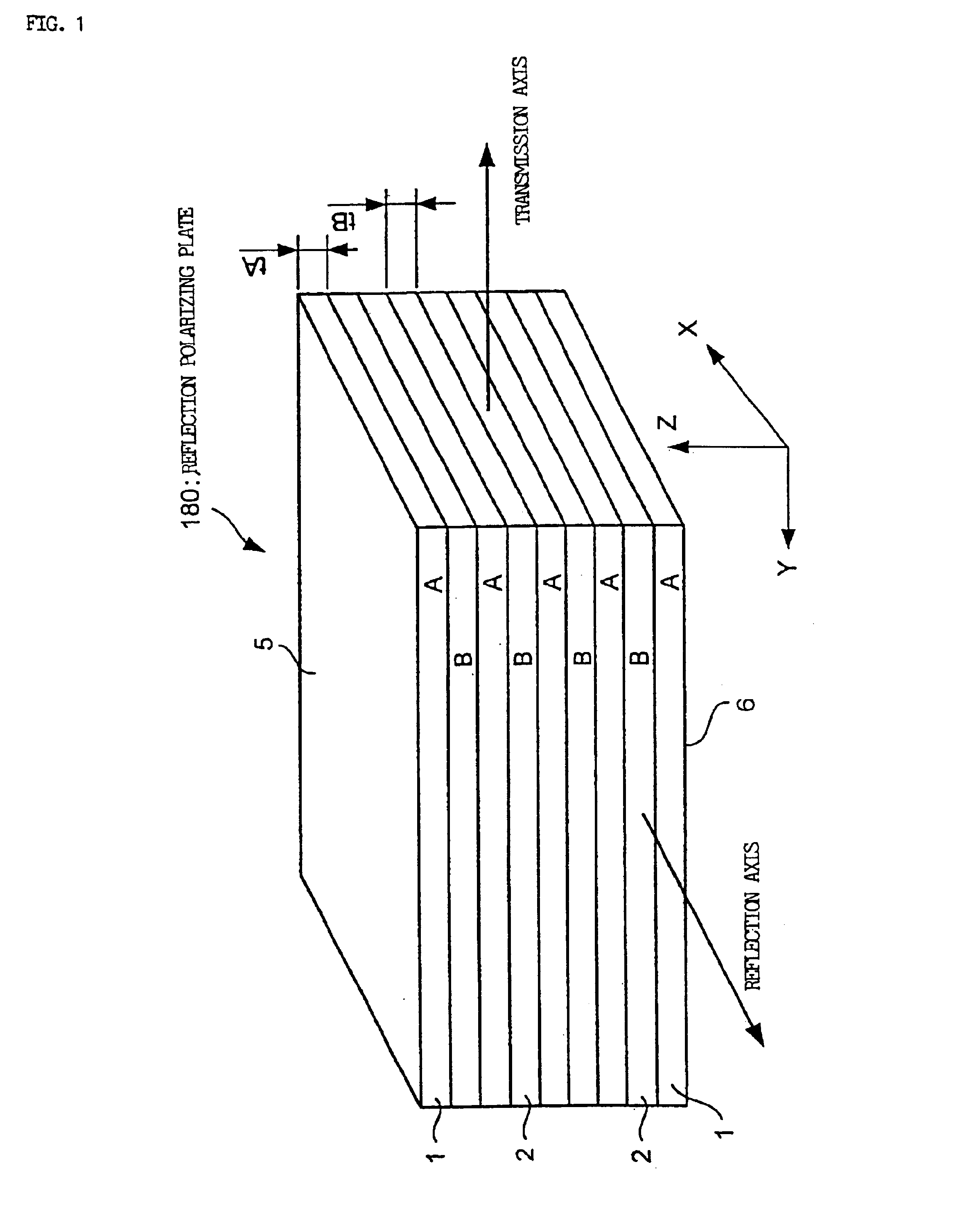
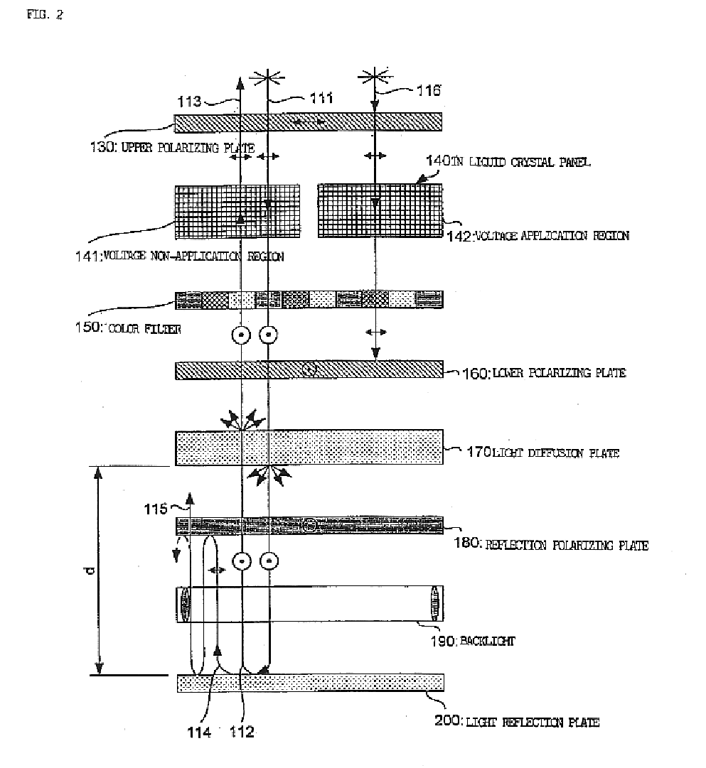
[0113]Further, the relationship bet...


PUM

PropertyMeasurementUnit
hazeaaaaaaaaaa
distanceaaaaaaaaaa
thicknessaaaaaaaaaa

Abstract

Above a TN liquid crystal panel 140, there is provided an upper polarizing plate 130, and below it, there are sequentially provided a color filter 150, a lower polarizing plate 160, a light diffusion plate 170, a reflection polarizing plate 180, a backlight 190, and a light reflection plate 200. And the relationship between the haze value H of the light diffusion plate 170 and the distance between the light diffusion plate 170 and the light reflection plate 200 is set so as to satisfy the formula: H≧−200d+140, whereby it is possible to sufficiently diffuse incident light 111 passing through the light diffusion plate 170 and reaching the light reflection plate 200; in the case of black and white display, a reduction in parallax is achieved, and in the case of color display, the reflected light can be made white.

Description

BACKGROUND OF THE INVENTION[0001]1. Industrial Field of the Invention[0002]The present invention relates to a display device and an electronic apparatus using the same and, in particular, to a reflection type liquid crystal display device which effects display by reflecting external light, and a transflective display device capable of being used both as a reflection type display device which effects display by reflecting external light and as a transmission type display device which effects display by transmitting light source light, and an electronic apparatus using the same.[0003]2. Description of the Related Art[0004]Hitherto, display devices using a liquid crystal panel have been of two types: reflection type display devices which effect display by using external light, and transmission type display devices in which light is applied from behind a liquid crystal panel.[0005]In the case of a reflection type display device, the quantity of light is reduced in a dark place, so that ...

Claims


Application Information

Patent Timeline
Patent Type & Authority Patents(United States)
IPC IPC(8): G02F1/1335G02F1/13G09F9/30G02F1/13357G09F9/00
CPCG02F1/13362G02F1/133536G02F2203/02G02F2001/133626G02F2001/133545G02F1/133545G02F1/133626G02F1/1335
Inventor IIJIMA, CHIYOAKI
Owner BOE TECH GRP CO LTD
Why Eureka
Try Eureka