
Liquid crystal panel and liquid crystal display

a liquid crystal display and panel technology, applied in the field of liquid crystal panel and liquid crystal display, can solve the problem of difficult to provide a neutral display that is free from coloring in every direction, and achieve the effect of high-quality display

Active Publication Date: 2012-09-25
NITTO DENKO CORP
View PDF62 Cites 1 Cited by
  • Summary
  • Abstract
  • Description
  • Claims
  • Application Information

AI Technical Summary

Benefits of technology

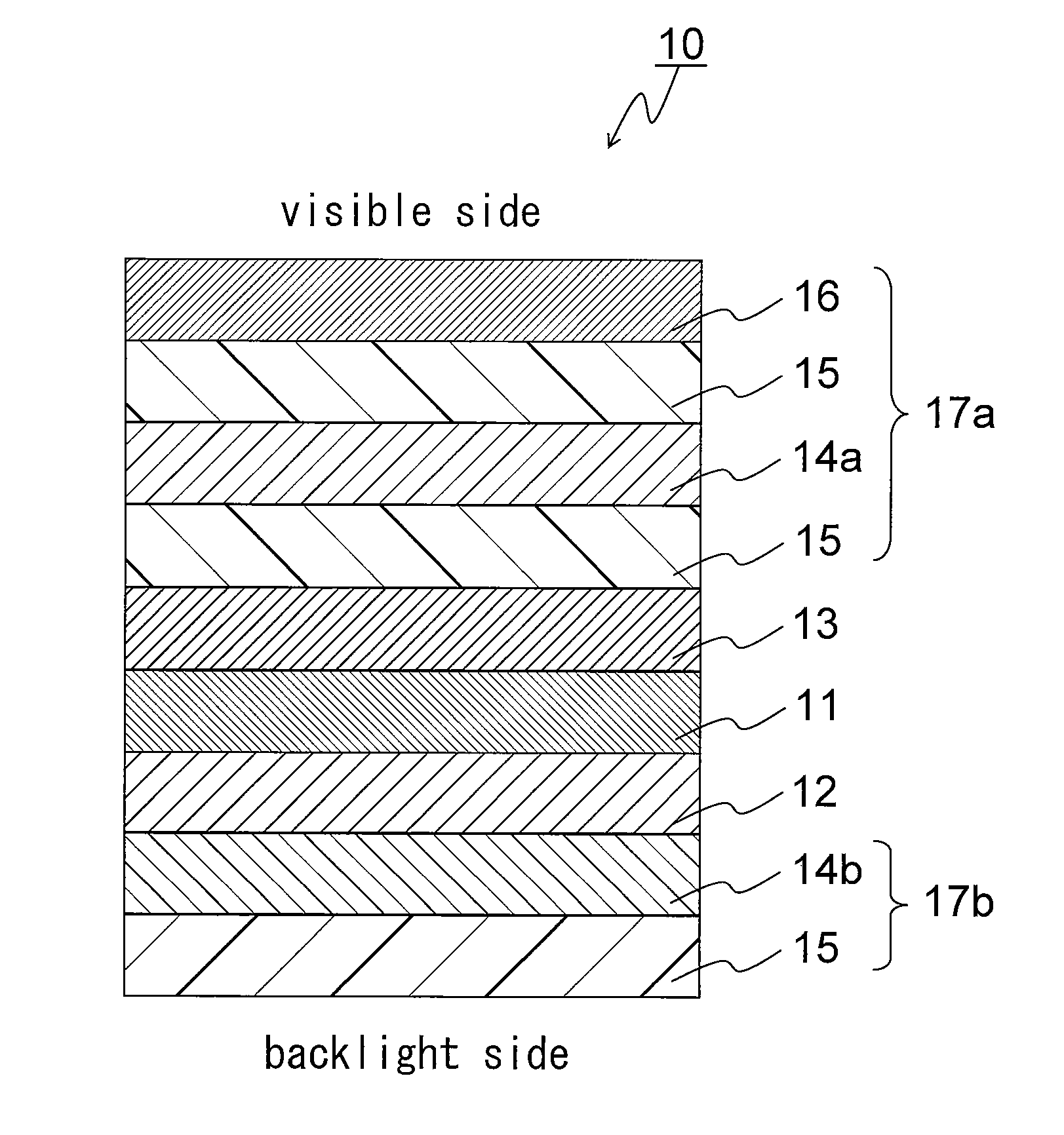
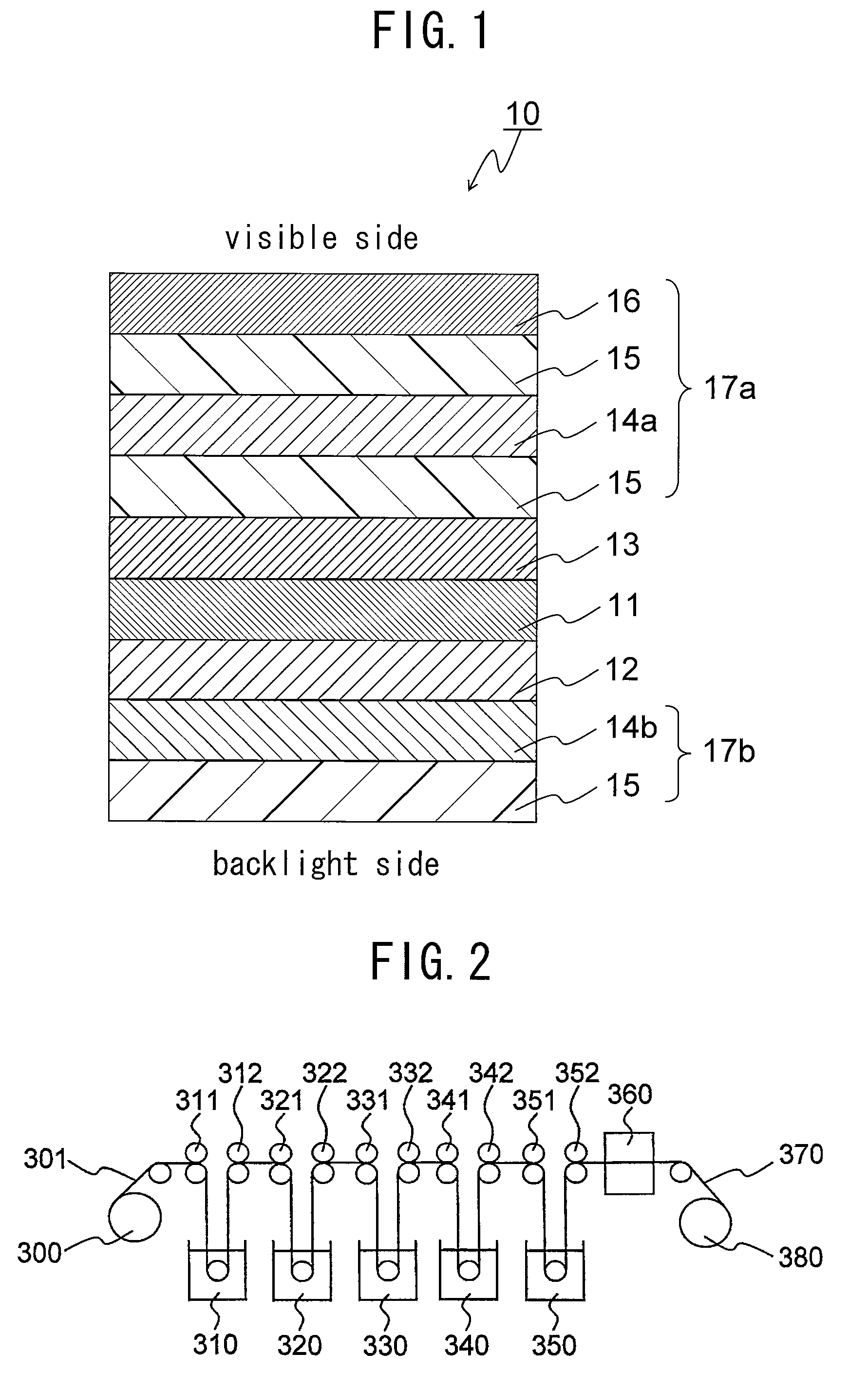
The present invention provides a liquid crystal panel and display that can produce a neutral display without color distortion in every direction. This is achieved by arranging a first polarizer, second polarizer, and liquid crystal cell, with a first retardation layer and second retardation layer between the liquid crystal cell and the second polarizer. The refractive index ellipsoids of the first and second retardation layers have specific relationships. The technical effect of this invention is a high-quality display with uniform display and reduced color distortion.

Problems solved by technology

However, with conventional liquid crystal panels, it is difficult to provide a neutral display that is free from coloring in every direction.

Method used


Image

  • Liquid crystal panel and liquid crystal display
  • Liquid crystal panel and liquid crystal display
  • Liquid crystal panel and liquid crystal display

Examples


reference example 1

[0212]A 75 μm thick polymer film containing a polyvinyl alcohol resin as a main component (Kuraray Co., Ltd., trade name “VFPS#7500”) was immersed in five baths in the conditions described in [1] to [5] below with a tensile force being applied in the longitudinal direction of the film, whereby the film was stretched so that the final stretch ratio would be 6.2 times its original length. This stretched film was dried in an air circulation oven at 40° C. for 1 minute. Thus, a polarizer (A) was produced.

[0213][1] Swelling bath: pure water at 30° C.[0214][2] Dye bath: an aqueous solution at 30° C. containing 0.032 parts by weight of iodine with respect to 100 parts by weight of water and 0.2 parts by weight of potassium iodide with respect to 100 parts by weight of water[0215][3] First crosslinking bath: an aqueous solution at 40° C. containing 3 wt % potassium iodide and 3 wt % boric acid[0216][4] Second crosslinking bath: an aqueous solution at 60° C. containing 5 wt % potassium iodid...

reference example 2

[0218]A polarizer (B) was produced in the same manner and under the same conditions as in Reference Example 1, except that, in the dye bath, the added amount of iodine described in the condition [2] was set to 0.031 parts by weight with respect to 100 parts by weight of water.

reference example 3

[0219]A polarizer (C) was produced in the same manner and under the same conditions as in Reference Example 1, except that, in the dye bath, the added amount of iodine described in the condition [2] was set to 0.027 parts by weight with respect to 100 parts by weight of water.

[0220][First Retardation Layer]


PUM

PropertyMeasurementUnit
transmittanceaaaaaaaaaa

Abstract

The present invention provides a liquid crystal panel that can provide a neutral display that is free from coloring in every direction. The liquid crystal panel includes a first polarizer 14a, a second polarizer 14b, and a liquid crystal cell 13. The first polarizer 14a is arranged on the visible side of the liquid crystal cell 13 and the second polarizer 14b is arranged on the backlight side of the liquid crystal cell 13. The liquid crystal panel further includes a first retardation layer 11 and a second retardation layer 12. A refractive index ellipsoid of the first retardation layer 11 has a relationship of nx=ny>nz, and a refractive index ellipsoid of the second retardation layer 12 has a relationship of nx>ny≧nz. The first retardation layer 11 and the second retardation layer 12 are arranged between the liquid crystal cell 13 and the second polarizer 14b.

Description

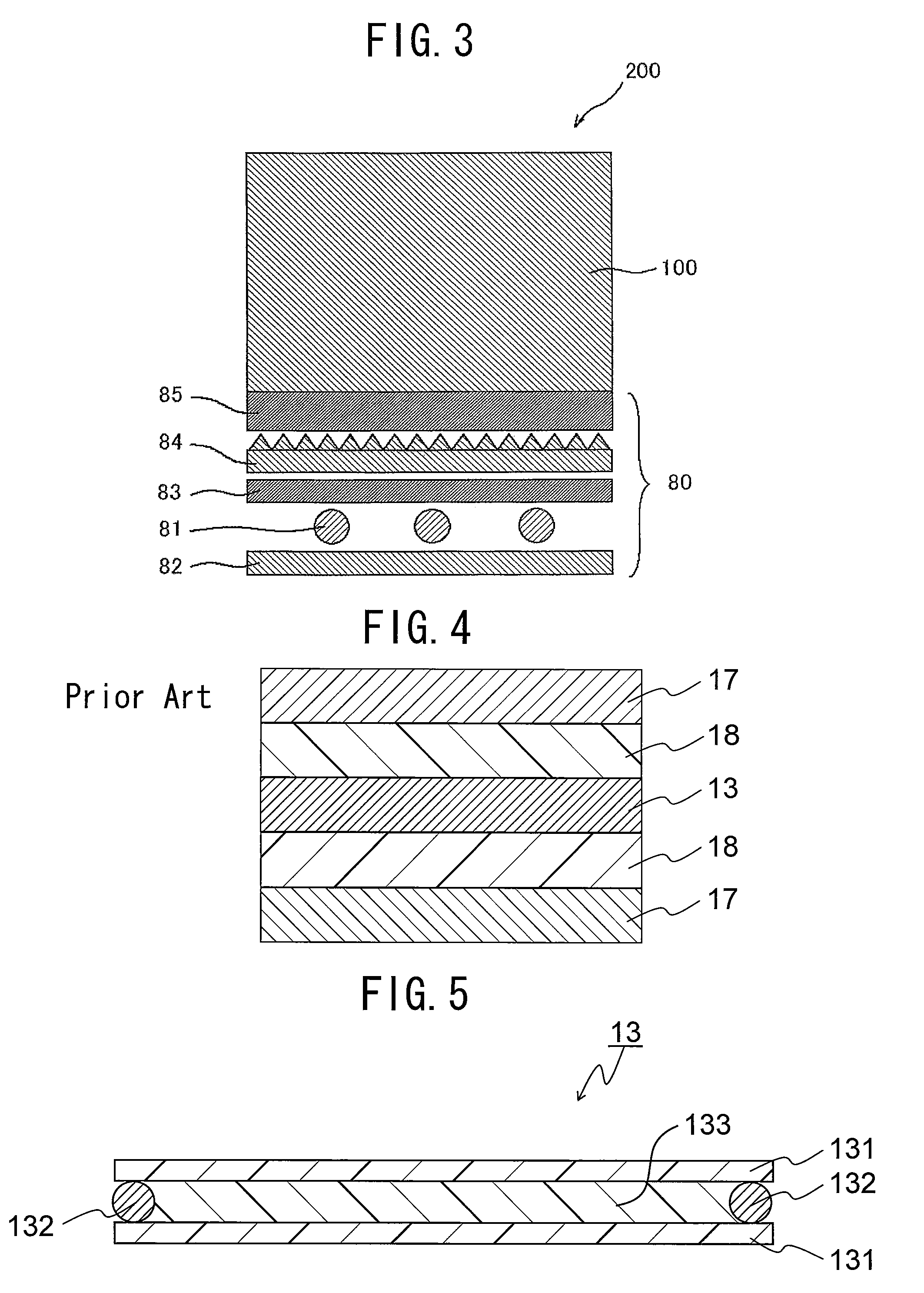
TECHNICAL FIELD[0001]The present invention relates to a liquid crystal panel and a liquid crystal display.BACKGROUND ART[0002]Liquid crystal displays (LCDs) are devices that display characters and images utilizing electro-optical characteristics of liquid crystal molecules, and they have been used widely in mobile phones, notebook computers, liquid crystal televisions, etc. In a LCD, a liquid crystal panel having a polarizing plate arranged on each side of a liquid crystal cell generally is used. For example, in a normally black type LCD, a black display can be obtained when no voltage is applied thereto (see Patent Document 1, for example). An example of the configuration of a conventional liquid crystal panel is shown in the schematic sectional view of FIG. 4. As shown in FIG. 4, polarizing plates 17 are arranged on both sides of a liquid crystal cell 13 with a retardation layer 18 intervening between the liquid crystal cell 13 and each of the polarizing plates. An example of the ...

Claims


Application Information

Patent Timeline
Patent Type & Authority Patents(United States)
IPC IPC(8): G02F1/1335
CPCG02F1/133528G02B5/3083G02B27/28G02F1/133634G02F2001/133531G02F2001/133607G02F2201/50G02F2202/40G02F2413/02G02F2413/07G02F2413/11G02F2413/12G02F1/133531G02F1/133607
Inventor KITAGAWA, TAKEHARUHAYASHI, DAISUKEISHIDA, HIDEKINISHIBE, TAKESHIMURAKAMI, NAO
Owner NITTO DENKO CORP
Learn More