Apparatus and method of measuring vibration quantity and method of designing loop

a technology of vibration quantity and apparatus, applied in the direction of instruments, disposition/mounting of heads, digital signal error detection/correction, etc., can solve the problems of unstable unnecessarily large bandwidth or gain of focus and tracking loop, etc., to achieve optimal focus and tracking loop

Inactive Publication Date: 2005-06-14
TS OPTICS CORP
View PDF7 Cites 23 Cited by
  • Summary
  • Abstract
  • Description
  • Claims
  • Application Information

AI Technical Summary

Benefits of technology

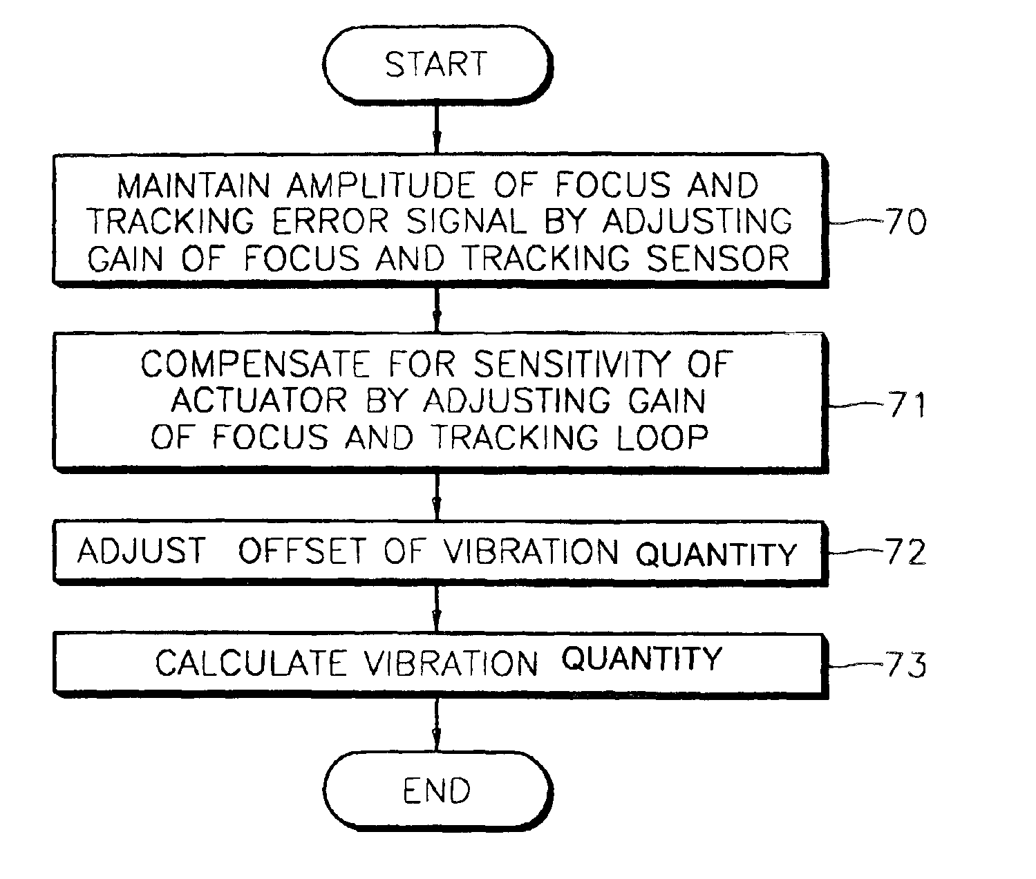
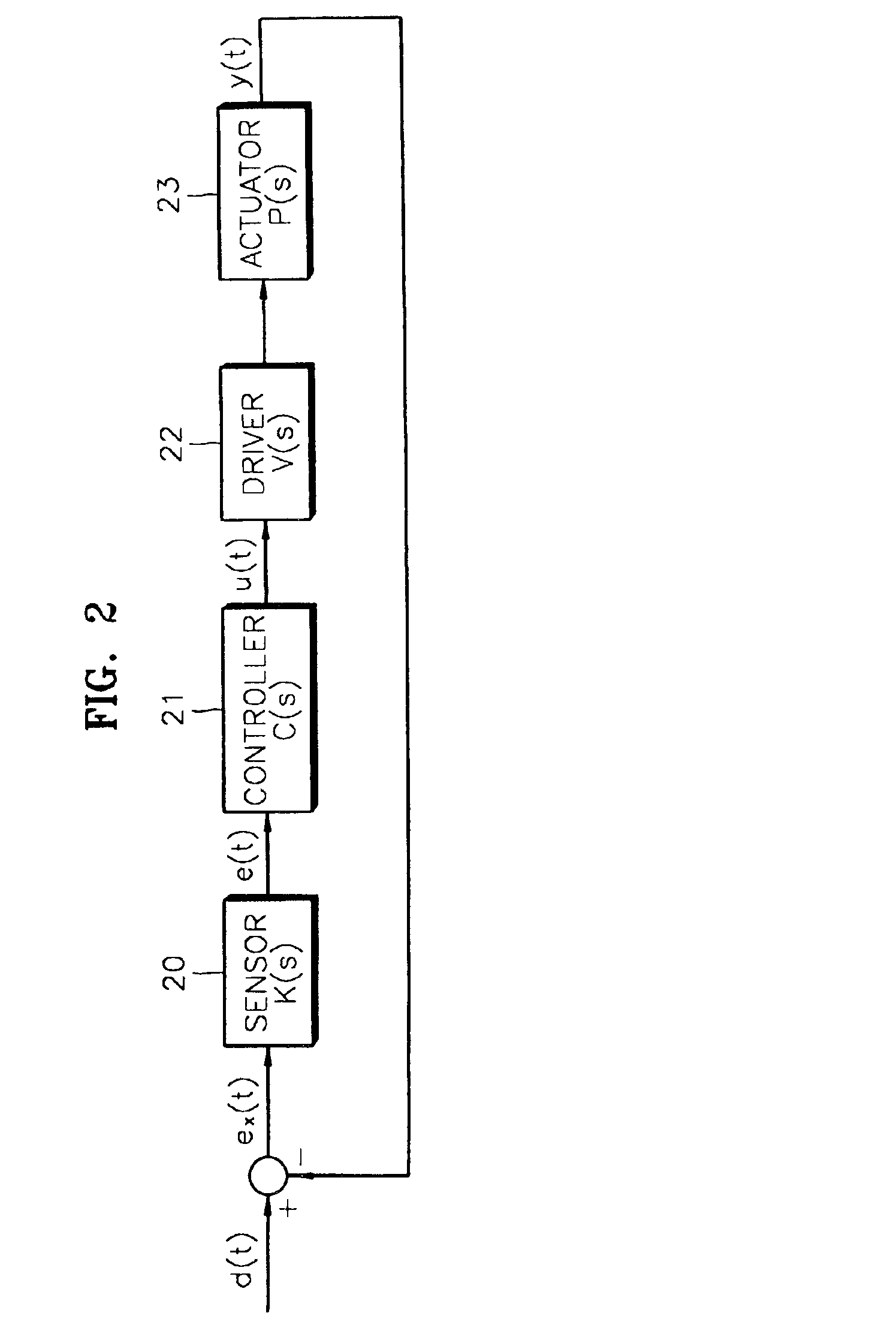
[0022]To achieve the above and other objects of the present invention, there is provided a loop design method of a method of measuring a vibration quantity in a disc recording and reproducing system having a focus and tracking loop including a controller which controls focus and tracking of a disc received in the disc recording and reproducing system and an actuator, in which a vibration occurs in the focus and tracking loop in response to rotating of the disc, the method comprising adjusting an amplitude of a focus and tracking error, which occurs in response to the rotating of the disc, so as to maintain the amplitude constant, compensating for a gain difference of an actuator, wherein the compensating for the gain difference comprises comparing a closed loop phase of the focus and tracking loop and a phase of a nominal closed loop, and adjusting a gain of the focus and tracking loop to be constant, calculating the vibration quantity based on the adjusted focus and tracking error and the adjusted gain of the focus and tracking loop, and an output of the controller which is compensated by the adjusted focus and tracking error and gain of the focus and tracking loop, and calculating a minimum gain of the focus and tracking loop by dividing the vibration quantity by a predetermined permissible error, and resetting the gain of the focus and tracking loop using the calculated minimum gain.

Problems solved by technology

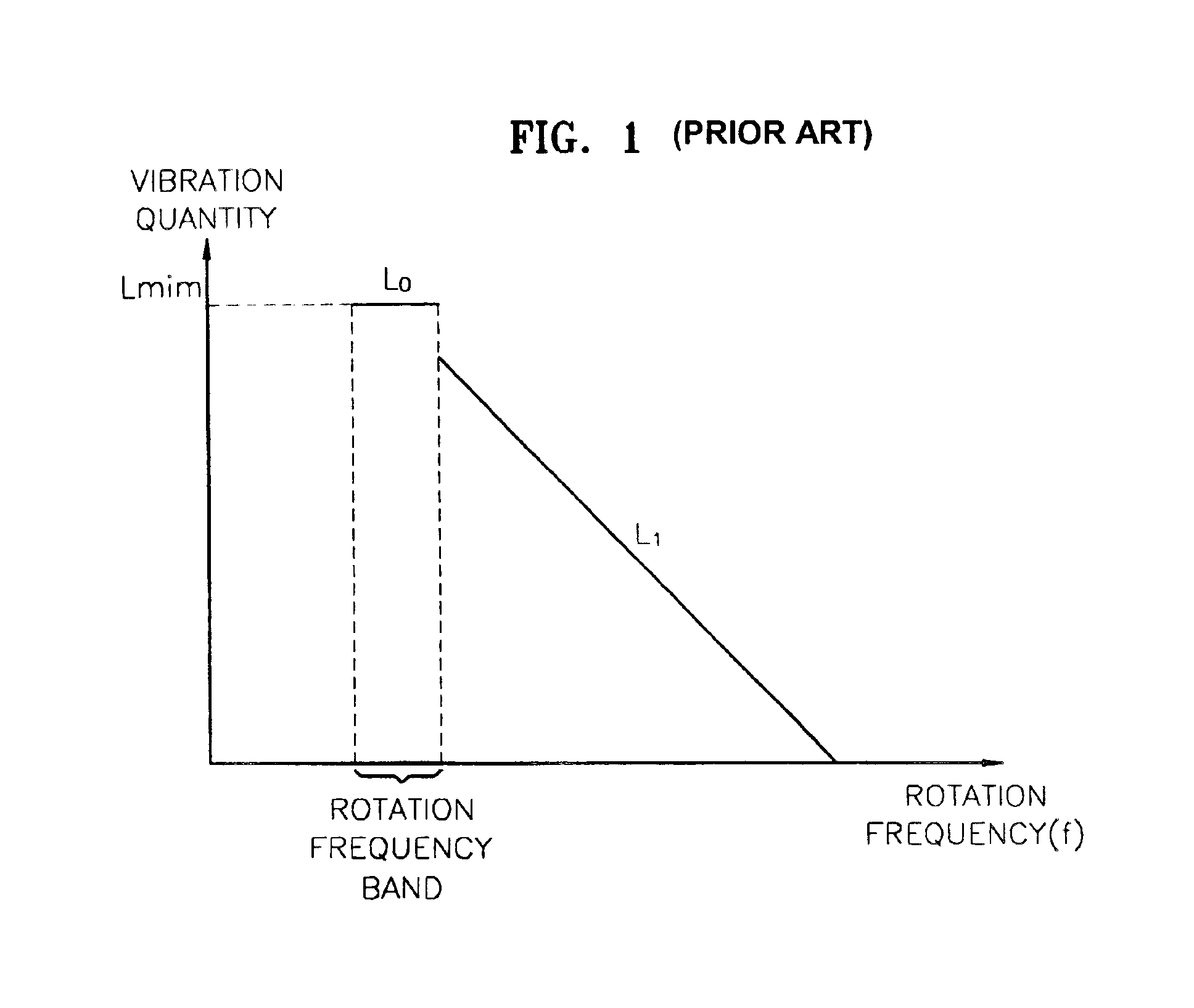
Therefore, where a focus and tracking loop is designed with these maximum vibration quantity and maximum vibration acceleration, a bandwidth or a gain of the focus and tracking loop becomes unnecessarily great, and an output of a block of the focus and tracking loop is saturated such that the focus and tracking loop is unstable.
Therefore, where the maximum vibration acceleration at the speed factor of n times is obtained by multiplying the maximum vibration acceleration at the speed factor of one time by the square of n, the maximum vibration acceleration value at a high speed factor becomes too great such that there is no reliability in data.
However, since it is difficult to measure the vibration in the tracking direction with the LDV, the maximum vibration acceleration for each speed factor cannot be measured.
In addition, since it is not accurately known how much the maximum vibration acceleration increases in accordance with an increasing speed factor, a minimum loop gain cannot be calculated where the speed factor increases.
Therefore, when an actual vibration quantity varies, which depends on the type of a disc and drive, the focus and tracking vibration quantity cannot be reliable data.

Method used


Image

  • Apparatus and method of measuring vibration quantity and method of designing loop
  • Apparatus and method of measuring vibration quantity and method of designing loop
  • Apparatus and method of measuring vibration quantity and method of designing loop

Examples


Embodiment Construction

[0032]Reference will now be made in detail to the embodiments of the present invention, examples of which are illustrated in the accompanying drawings, wherein like reference numerals refer to the like elements throughout. The embodiments are described below in order to explain the present invention by referring to the figures.

[0033]Where a speed factor of a drive changes, a frequency characteristic of a vibration quantity changes, and a focus and tracking loop should be redesigned. If a disc (not shown) being driven is replaced, a focus and tracking loop should be redesigned due to the structure and signal characteristic of the disc. Thus, in a drive (not shown) which has to accommodate many speed factors and disc types, a controller (not shown) should be redesigned for each disc type and speed factor, and the designed data should be maintained in a micom (not shown).

[0034]For example, a DVD recording and reproducing apparatus should reproduce data from or record data on discs such...


PUM

PropertyMeasurementUnit
focal lengthaaaaaaaaaa
phaseaaaaaaaaaa
vibration accelerationaaaaaaaaaa

Abstract

A vibration quantity measuring apparatus and method, and a loop design method in which a vibration quantity generated in a focus and tracking loop is accurately measured to optimally design a focus and tracking loop of an optical disc drive. The vibration quantity measuring apparatus includes an error gain adjusting unit which adjusts an amplitude of a focus and tracking error which occurs where a disc rotates, so as to maintain the amplitude of the focus and tracking error constant, a loop gain adjusting unit which compares a closed loop phase of a focus and tracking loop and a predetermined reference closed loop phase, and maintains a constant gain of the focus and tracking loop to compensate for a gain difference of an actuator, and a measuring unit which calculates and outputs a vibration quantity using an error adjusted by the error gain adjusting unit and the loop gain adjusting unit, and an output of a controller which controls a focus and tracking of the disc. According to the methods and apparatus, a focus and tracking vibration quantity that occur differently depending on the type of a disc, on which data is recorded on or read from, or depending on a speed factor of a disc drive, can be measured.

Description

CROSS-REFERENCE TO RELATED APPLICATIONS[0001]This application claims the benefit of Korean Application No. 2001-52561 filed Aug. 29, 2001, in the Korean Intellectual Property Office, the disclosure of which is incorporated herein by reference.BACKGROUND OF THE INVENTION[0002]1. Field of the Invention[0003]The present invention relates to an apparatus and a method of measuring a vibration quantity, and a loop design method in which a vibration quantity generated in a focus and tracking loop is accurately measured to optimally design a focus and tracking loop of an optical disc drive.[0004]2. Description of the Related Art[0005]Where data is recorded on or read from an optical disc, an optical disc drive should accurately focus a recording surface of the optical disc with a focus servo, and have a pickup which accurately follows a track with a tracking servo. A focus and tracking loop should be accurately modeled to accurately control the focus and tracking servos. A focus and trackin...

Claims


Application Information

Patent Timeline
Patent Type & Authority Patents(United States)
IPC IPC(8): G01H1/00G11B20/18G11B19/02G11B7/09G11B7/00G11B7/095
CPCG11B7/094G11B7/0941G11B7/0946G11B7/0953G11B7/0948G11B19/02
Inventor LEE, MOON-NOHKIM, WONGO, SUNG-ROLEE, DONG-JINYANG, HYUN-SEOKJUN, HONG-GUL
Owner TS OPTICS CORP
Why Eureka
Try Eureka